How to achieve high power transmission to rotary joints?
The rotary joint is an important functional device on the high-power microwave transmission line. It can ensure the normal transmission of electromagnetic energy in the feeder line while the high-power transmission line is mechanically rotating. It is a key device to ensure that the mechanical scanning radar can smoothly transmit and receive electromagnetic waves in all directions.
Generally, a rotary joint is composed of a rotor, a stator and a choke structure connected to each other, and a gap is left between the stator and the rotor so that the two can rotate. But the discontinuity of the waveguide structure will lead to the problem of microwave leakage and increased reflection. What’s more serious is that in the case of high power, the discontinuity of the waveguide structure will easily lead to excessive local field strength of the system, resulting in power breakdown of the system. The existence of the choke structure is to achieve the purpose of efficient microwave transmission while realizing mechanical rotation. How to achieve high power transmission? One way to do this is described below.
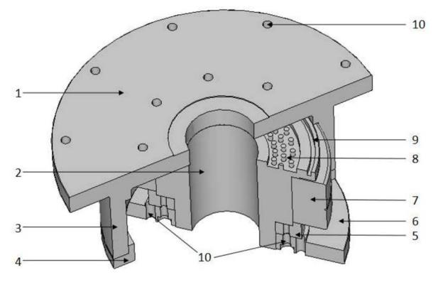
This kind of high-power multi-mode broadband rotary joint includes a rotor circular waveguide, a stator circular waveguide, and a bearing structure; the rotor circular waveguide and the stator circular waveguide are over-molded circular waveguides with the same caliber and coincident central axes, passing through the bearing structure Realize relative rotation; there is a certain distance between the adjacent end surfaces of the rotor circular waveguide and the stator circular waveguide to ensure that the two can realize relative rotation.
It is characterized in that the rotary joint further includes a gap waveguide choke structure arranged at the end faces of the rotor circular waveguide and the stator circular waveguide;
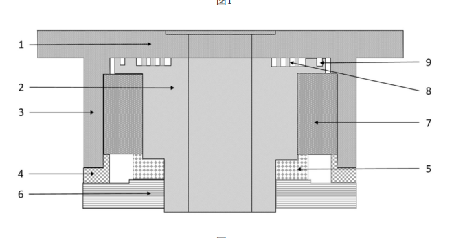
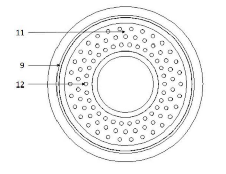
The gap waveguide choke structure includes an annular groove arranged on the end face of the stator circular waveguide, and an array of metal cylinders arranged in the annular groove; the array of metal cylinders includes three concentric ring arrays arranged at equal intervals, each concentric The ring arrays are composed of N metal cylinders evenly arranged, and the adjacent concentric ring arrays are staggered by half a period, so that any metal cylinder and two metal cylinders adjacent to the adjacent layer form an isosceles triangle. This structure acts as the main choke structure of the rotary joint to suppress the leakage of electromagnetic waves from the port gap.
In order to meet the requirements of high-power microwave transmission and multi-mode operation, this product uses two over-molded circular waveguides with the same caliber and coincident central axis as the main waveguide of the rotary joint. There is a small distance between the two adjacent end faces, so that they can realize relative rotation without contact.
In order to prevent the electromagnetic wave energy from leaking from the end face gap, this product has designed a gap waveguide choke structure on the end face as the main choke structure of the rotary joint. The gap waveguide choke structure is a periodic structure, one side of which is a smooth metal plane, and the other side is a periodic array of metal cylinders. Different parts of the structure do not need electrical contact, which is well in line with the structural requirements of the rotary joint.
The metal cylindrical periodic array can simulate a high impedance plane, and forms an electromagnetic bandgap structure with the metal plane, preventing electromagnetic waves from propagating in the parallel plate waveguide. At the same time, the periodic unit has a wide electromagnetic band gap, and introducing it into the choke structure can effectively improve the working bandwidth of the rotary joint.
For higher-order modes with higher cut-off frequency, the waveguide wavelength is larger, and a smaller arrangement period and cell size are required to suppress the propagation. Therefore, the realization of multi-mode must be at the cost of bandwidth reduction. The quarter-wavelength impedance conversion structure mentioned above will also produce the problem of the trade-off between multimode and bandwidth. This rotary joint design does not require the use of a mode conversion structure, making it capable of not being limited to specific mode inputs.
The applicability to multiple propagation modes requires its choke structure to have the characteristics of wide-band operation, while the gap waveguide choke structure has a wide band gap, even considering multiple adjacent modes can maintain good electromagnetic waves in a band inhibition.
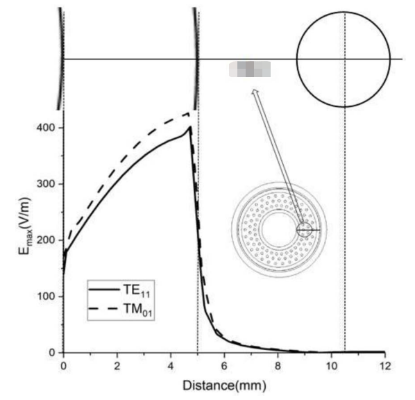
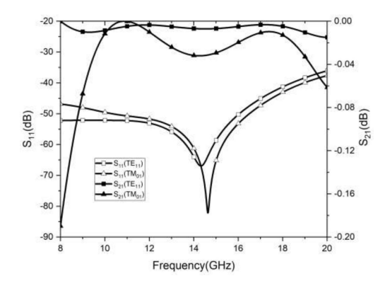
For the required high-power microwave radar system, high-order modes above TE01 mode are rarely used in rotary joints. The cut-off frequency of TE01 mode can be used to determine the aperture size of the over-mode circular waveguide, thereby suppressing the generation of high-order modes. The field strength of the TE01 mode is concentrated in the center of the circular waveguide, and the fringe field is small, and it will hardly leak from the seam even if there is no corresponding choke structure; while the low-order modes such as TE11 have similar cut-off frequencies, even if these modes are considered at the same time The swivel joint still has sufficient bandwidth, so this optional joint can meet both multimode and broadband requirements.
The notable advantages of this product are:
- Through the combination of the gap waveguide structure and the choke coil structure, this product can effectively reduce the field strength at the joint of the rotary joint. It is suitable for the transmission of high-power microwaves and has high power capacity and low propagation loss.
- Based on the gap waveguide technology, this product has a wide operating frequency and can realize high-efficiency transmission of microwaves within a relative bandwidth of more than 80%.
- This product eliminates the mode conversion structure, and the overall structure is more compact. At the same time, it is no longer limited to the input of a specific mode and can support the transmission of multiple circular waveguide modes in the rotary joint.
- This product can flexibly adjust the size of the periodic structure according to the needs, so as to meet the requirements of the working frequency band in actual use.
- This product is a non-contact rotary joint, which reduces the wear of the connecting parts and has a longer service life.