Improvement scheme of capacitive coaxial radio frequency rotary joint
With the further development of radar technology, the quality requirements for the data transmitted by the rotating part are getting higher and higher, and the amount of data transmission is increasing. In addition to the high-precision inner and outer conductors, the most important thing for the stability of signal transmission is stable coupling. gap. However, the brushes of traditional slip rings are easy to wear and other problems, which are not suitable for the use of radar.
The complex structure of the rotary joint lies in the joint limitation. Sometimes, some special cases may need to control the joint angle. Joint limits enforce joint angles to remain within a certain range. to limit the free rotation of the object on the revolute joint. In joint limits, include zero values for the joint angles, otherwise objects will be tilted when starting the simulation.
The capacitive rotary joint is the most widely used rotary joint. The structure of the capacitive rotary joint is a stator component and a rotor component, and the two components are directly assembled into a whole.
According to the current manufacturing technology, commercially available capacitive rotary joints are generally dual-channel rotary joints, which are composed of internal and external channels, and each channel is composed of internal and external conductors. The transmission performance stability, delay stability and consistency are poor, and the performance is poor The cause of the difference is caused by the difference in concentricity of the mechanical assembly of the inner and outer conductors or the deformation of the inner and outer conductors caused by the temperature cycle.
This commercially available capacitive rotary joint adopts channel separation assembly design, and the assembly coaxial error is relatively large. Moreover, the dual-channel signal transmission conductor is thin (0.5mm), and the non-contact capacitive isolation gap is as small as 0.2mm. It is difficult to ensure the cylindricity and coaxiality of the rotary joint during the manufacturing and assembly process. Therefore, the existing capacitive dual-channel rotary joint has short service life, poor stability of delay transmission performance and difficult assembly.
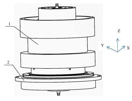
In order to improve the problem of poor concentricity and poor concentricity stability of the capacitive rotary joints in the prior art, the two components of the rotor assembly 1 and the stator assembly 2 are directly assembled into a composite coaxial assembly of the capacitive rotary joint as shown in the figure.
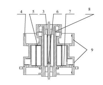
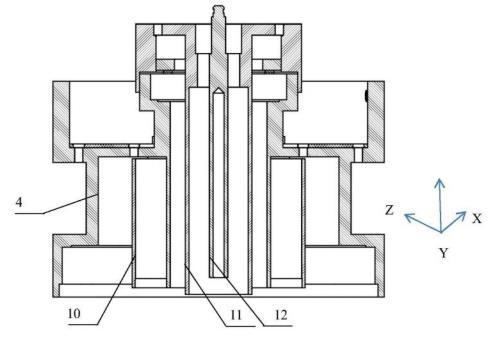
The channel uses dielectric structural parts to isolate the internal and external transmission channels. The inner channel of the rotor assembly 1 is isolated by the dielectric sleeve 3 covering the cylindrical coupling conductor mandrel and the dielectric limit block 6 at the bottom of the hollow blind hole of the cylindrical coupling conductor mandrel. The channel adopts the slip ring dielectric sleeve 5 covering the cylinder of the rotor assembly 1 and the stator dielectric sleeve 7 as the outer shielding ring to isolate the transmission joints. The internal and external transmission channels are separated by the adaptive coaxial transmission medium. The gap between the rotating cylinders can be controlled with high precision.
This kind of medium isolation method ensures that during the joint rotation process, the gap between the inner and outer channels is uniform, and the medium material has wear resistance, self-lubricating properties, and appropriate strength. The defect of poor assembly concentricity of the inner and outer conductors of the capacitive rotary joint is overcome.
Adaptive coaxial transmission medium isolation and composite coaxial assembly are used to adjust the gap between the rotating drums and control the gap with high precision.
During joint rotation, the inner channel stator assembly and the inner channel rotor assembly rely on the medium sleeve 3 and the medium stop block 6 to always ensure uniform running clearance, and the outer channel is isolated by the medium sleeve 5 and the stator medium sleeve 7 . In addition, the composite coaxial assembly method is adopted in the structure to ensure the assembly accuracy of the rotor assembly and the stator assembly, and greatly improve the assembly efficiency of the rotary joint.
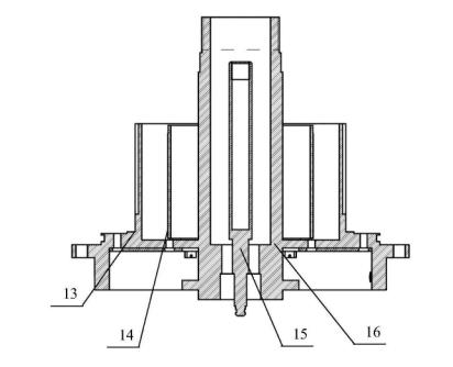
During joint rotation, the outer channel stator assembly and the outer channel rotor assembly rely on the dielectric sleeve 5 and the stator dielectric sleeve 7 to always ensure a uniform running gap and achieve long-term stability of signal coupling. Conductor concentricity or concentricity stability, its performance is stable, channel transmission standing wave and transmission loss decrease, can be controlled below 3%.
The high-strength isolation ring can react on the coupling conductor of the thin-walled structure, so that the roundness of the coupling conductor can be self-adaptively repaired, and the coupling gap is more uniform;
In addition, the high-hardness isolation ring can ensure wear resistance. Even if it is used for a long time, the wear amount is extremely small. The material and special structural design with these two functions can not only ensure the static accuracy of the rotary joint, but also ensure the dynamic accuracy, which is greatly improved. The long-term stability of the signal coupling of the rotary joint is improved, and the problems of short service life and poor stability of delay transmission performance of the existing capacitive dual-channel rotary joint are solved.