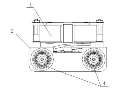
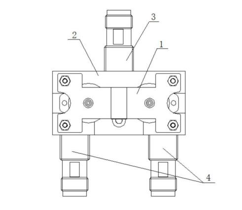
A Y-type SPDT RF coaxial switch
RF coaxial switches are widely used in RF/microwave systems, such as time multiplexers, time division channel selection, pulse modulation, transceiver switching, beam adjustment, etc.
At present, the RF input interface and the RF output interface of most RF coaxial switches are fixed on the same side, resulting in complicated connection cables between the RF input interface and the RF output interface, which occupy a large space and small operating space. And the contact between the inner conductor of the radio frequency input interface and the radio frequency output interface and the radio frequency reed is surface-to-surface or point-to-face contact, and the contact position between the inner conductor and the radio frequency reed is always fixed. When there is pollution between the inner conductor and the contact of the radio frequency reed , will increase the contact resistance, poor contact, and product failure.
The technical problem to be solved is to provide a Y-type single-pole double-throw radio frequency coaxial switch, and the radio frequency input interface and two radio frequency output interfaces are respectively arranged on both sides of the radio frequency system, so that the connecting cables between the interfaces are simple and the space is compact , large operating space.
The improvement plan is:
It is realized by a Y-type single-pole double-throw radio frequency coaxial switch, including an electromagnetic system, a radio frequency system, a radio frequency input interface and two radio frequency output interfaces connected to the radio frequency system;
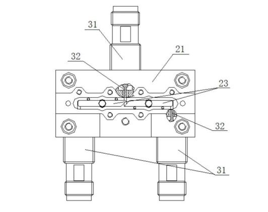
This system includes a radio frequency cavity, two push rods set in the radio frequency cavity and a radio frequency reed fixedly connected to each push rod. Each groove is provided with a spring and a push rod, and the two ends of the spring are in contact with the groove bottom of the guide groove and the bottom end of the corresponding push rod respectively.
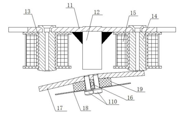
When the spring is not stressed, the upper parts of the two push rods protrude out of the guide groove and the upper parts of the two push rods are fixed with horizontally arranged radio frequency reeds. At this time, the two radio frequency reeds are located at the same height and arranged coaxially , the tops of the two push rods are located directly below the driving mechanism of the electromagnetic system.
The outer conductor of one radio frequency input interface is fixed on the outer wall of one of the side plates of the radio frequency cavity, the outer conductors of the two radio frequency output interfaces are fixed on the outer wall of the other side plate of the radio frequency cavity, and the radio frequency cavity is fixed with the radio frequency input interface One side board and the other side board fixed with the radio frequency output interface of the radio frequency cavity are parallel to each other.
The inner ends of the cylindrical inner conductors of one radio frequency input interface and two radio frequency output interfaces extend horizontally into the radio frequency cavity, and the axes of the cylindrical inner conductors of one radio frequency input interface and two radio frequency output interfaces are perpendicular to the radio frequency reed The inner end of the cylindrical inner conductor of the radio frequency input interface is located directly below the inner ends of the two radio frequency reeds, and the inner ends of the cylindrical inner conductors of the two radio frequency output interfaces are respectively located directly below the outer ends of the two radio frequency reeds.
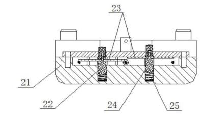
The magnetic system includes a yoke, two iron core windings, a magnetic steel column, a supporting shaft, an armature piece and a moving reed.
The tops of the two iron core windings and the magnetic steel columns are fixed on the yoke and the magnetic steel columns are located between the two iron core windings, and the support shaft is horizontally set and located directly below the magnetic steel columns;
The armature sheet is a sheet-like structure bent in the middle, and the bending angle is an obtuse angle. The moving reed is a flat sheet structure, the obtuse angle of the armature piece faces the moving reed and the two are fixedly connected as a whole, the middle part of the armature piece and the moving reed are both rotatably connected to the support shaft, and the two ends of the armature piece are respectively located on the two sides. directly below the core winding;
The top ends of the two push rods are located directly below the two ends of the moving reed.
For the permanent magnetic steel column, the magnetic steel column with the magnetic flux on the right side greater than the magnetic flux on the left side is selected.
A supporting block is interposed between the armature piece and the moving reed, and the fixing bolt passes through the moving reed, the supporting block and the armature piece to fix and connect the three as a whole. The two core windings both include a winding support, an iron core fixed to the inner ring of the winding support, and a coil winding wound on the winding support and located on the outer periphery of the iron core. The bottom of the iron core protrudes out of the winding support.
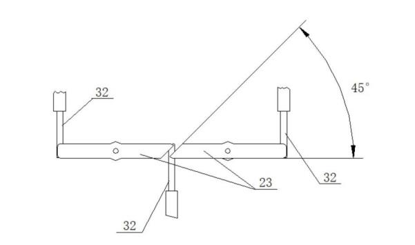
The inner ends of the two radio frequency reeds are beveled structures, the beveled surfaces of the inner ends of the two radio frequency reeds are parallel to each other, and the beveled angles are both 45 degrees.
Both a radio frequency input interface and two radio frequency output interfaces include an outer conductor, a cylindrical inner conductor and an insulating ring arranged in the outer conductor, and the insulating ring is a circular insulating ring located between the outer conductor and the cylindrical inner conductor.
Advantages of this program:
(1) The radio frequency input interface and two radio frequency output interfaces are respectively arranged on both sides of the radio frequency cavity, so that the connecting cables between the interfaces are simple, the space is compact, and the operation space is large.
(2) In the radio frequency system, the cylindrical inner conductors of the radio frequency reed, the radio frequency input interface and the two radio frequency output interfaces are all arranged horizontally, and the radio frequency reed is perpendicular to each cylindrical inner conductor respectively, and the lower end surface of the radio frequency reed It has a line contact structure with the side wall of the cylindrical inner conductor.
Since the cylindrical inner conductor can rotate circumferentially in the outer conductor, when the RF reed presses down on the cylindrical inner conductor, the cylindrical inner conductor will rotate at a small angle, so that the cylindrical inner conductor rotates to move the pollution at the top to the gap between the two. The outside of the contact wire makes the cylindrical inner conductor self-cleaning and has strong anti-pollution ability, ensuring effective contact between the cylindrical inner conductor and the radio frequency reed.
(3) The structure of the electromagnetic system is simple, and the dislocation drive of the two push rods can be realized by using one moving reed, so as to realize the separate control and driving of the two radio frequency reeds, that is, when one radio frequency reed moves down and conducts, the other The RF reed remains at rest.
(4) The inner ends of the two radio frequency reeds are set to a 45-degree oblique cut structure, which ensures that the two radio frequency reeds do not interfere when they move up and down, and when the radio frequency reeds are in contact with the cylindrical inner conductor, there is enough Strong strength, not easy to deform.