How to ensure the excellent EMC compatibility of the TTL control coaxial switch?
The coaxial switch uses the coaxial connector as the RF terminal, switches or selects the microwave signal channel on demand, and realizes high-quality signal transmission components. It is used in satellite communication, electronic countermeasures, radar, automated test equipment, and mobile communication systems. and so on are widely used.
The coaxial switch structure is divided into SPDT, DPTD, SPMT, DPMT, and other types. TTL control, etc. In the TTL control circuit, a TTL circuit and a coil-rated power supply circuit are generally used. The two circuits must share the ground. The TTL voltage controls the triode conduction, thereby turning on the power supply voltage, controlling the coil, and realizing the radio frequency channel. and switching of auxiliary contacts.
The biggest factor affecting electromagnetic compatibility (EMC) here is that the rated voltage and the TTL voltage must share the same ground, that is, the negative poles of the two external power supplies need to be connected, and the two power supplies cannot be physically isolated. When the circuit is working, the power supply voltage and the switch coil The reverse peak voltage will impact the TTL voltage, which cannot meet the electromagnetic compatibility (EMC) requirements in special environments.
The current solution to the technical problem is to provide a TTL-controlled magnetically latched coaxial switch control circuit with a load end, which satisfies the isolation and dual power supply functions at the same time, which can eliminate the influence of circuit noise and reverse peak voltage on the TTL circuit. Although it may cause an increase in cost when the corresponding performance is met.
When actual manufacturers choose products, it is best to understand the environment they are using to avoid unnecessary expenses.
Its technical solution is:
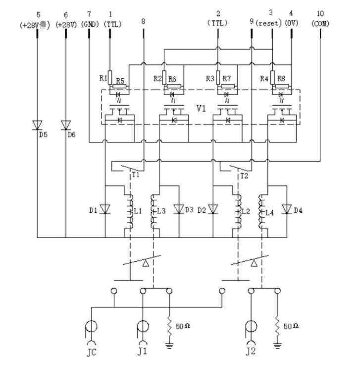
The TTL control magnetically latching coaxial switch control circuit with load end includes a power coil, a radio frequency input port, a radio frequency output port, and a photoelectric isolation relay. The two ends of the relay light detector are respectively connected to one end of the power coil and the ground, the other end of the power coil is connected to the positive pole of the power supply, and a radio frequency switch is connected between the radio frequency input port and the radio frequency output port, and the radio frequency switch corresponds to the power coil The normally open contact, that is, the power coil is energized, and the RF switch is closed.
The photoelectric isolation relay includes a TTL control photoelectric isolation relay and a reset photoelectric isolation relay, and the two ends of the light emitting diode of the TTL control photoelectric isolation relay are respectively connected to the TTL control terminal and the ground, and the two ends of the TTL control photoelectric isolation relay photodetector are respectively Connect one end of the power supply coil to the ground, connect the two ends of the light-emitting diode of the reset photoelectric isolation relay to the positive pole and the negative pole of the reset switch, respectively connect the two ends of the reset photoelectric isolation relay photodetector to one end of the reset coil and ground, and the other end of the reset coil Connect to the positive pole of the power supply, the RF switch is a double-throw switch, the movable end of the RF switch is connected to the RF output port, the two fixed ends of the RF switch are respectively connected to the RF input port and the grounding end, the power supply coil is energized, and the RF input port The conduction between the port and the RF output port, the reset coil is powered on, and the conduction between the RF output port and the ground terminal.
Its circuit includes multiple photoelectric isolation relays, multiple TTL control terminals, reset switches, power supply coils, reset coils, and radio frequency switches. Each photoelectric isolation relay includes a corresponding TTL control photoelectric isolation relay and resets photoelectric isolation relay. Each photoelectric isolation relay is correspondingly connected with a TTL control terminal, a reset switch, a power supply coil, a reset coil, and a radio frequency switch to form a TTL control circuit.
Its circuit has an auxiliary indicator switch, which is connected to the indicator circuit, and the auxiliary indicator switch is a normally open contact corresponding to the power coil, that is, the power coil is energized, and the auxiliary indicator switch is closed. There is a backup power supply, the positive pole of power supply and the positive pole of the backup power supply is connected to the other end of the power supply coil, and the positive pole of power supply and the positive pole of the backup power supply terminal is connected to the other end of the reset coil.
The specific working principle will not be described in detail.
The illustration is as follows.
Advantage:
- Eliminate the influence of circuit noise and reverse peak voltage on the TTL circuit, and meet the requirements of electromagnetic compatibility (EMC).
- There is a backup power supply. When the main power supply is abnormal, the backup power supply will be automatically connected, which will not affect the normal operation of the coaxial switch and improve the reliability of the circuit.
- A diode connected in parallel with the power supply coil and the reset coil is provided to suppress the reverse peak voltage of the coil.
Rotary-Tek’s design team are experts who have been engaged in the RF industry for many years and can bring users possible and high-quality coaxial switch products. Satisfying customers and serving customer service is also the philosophy we have been adhering to for many years.