Design of W-band Electromechanical Waveguide Switch
W-band, because its frequency is in the millimeter-wave atmospheric window and has the advantages of both microwave and infrared, such as: absolute frequency bandwidth, short wavelength, narrow beam, etc., is a very important section of the electromagnetic wave spectrum. It is used in high-resolution radar, High-precision positioning and guidance and high-speed communication have great application prospects.
With the development of technology, the application of W-band is becoming more and more mature, the function of microwave system is becoming more and more powerful, and the number of channels is increasing. In order to switch signals between different channels, it is inevitable to use microwave switches.
However, the most commonly used coaxial microwave switch in low-frequency systems cannot be applied to the W-band due to its own structural characteristics and the limitations of current processing accuracy. Although there are PIN waveguide switches working in the W-band, their small power capacity and narrow operating frequency band cannot meet the needs of high-power, wide-band microwave systems, and PIN waveguide switches also have large insertion loss, low isolation, and low VSWR. Poor cons.
Waveguide switches are commonly used devices in microwave electronic equipment. Compared with other microwave switches, electromechanical microwave waveguide switches have the characteristics of low voltage standing wave ratio, small insertion loss, and large power capacity. They have been widely used in radar, electronic countermeasures, etc. in low frequency bands. system.
In order to meet the needs of future microwave systems for W-band high-power capacity, broadband, and high-performance microwave switches, the following design ideas for waveguide switches are available.
1. Working principle
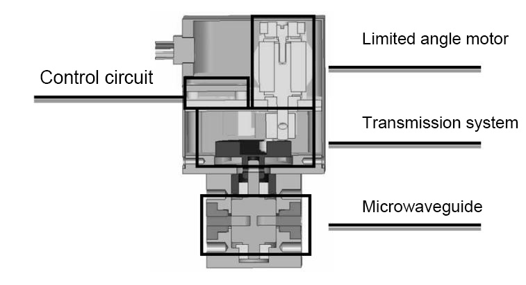
This paper develops a double-pole double-throw waveguide switch, which is composed of four parts: the control circuit, the limited rotation angle motor, the transmission system and the microwave system, as shown in Figure 1.
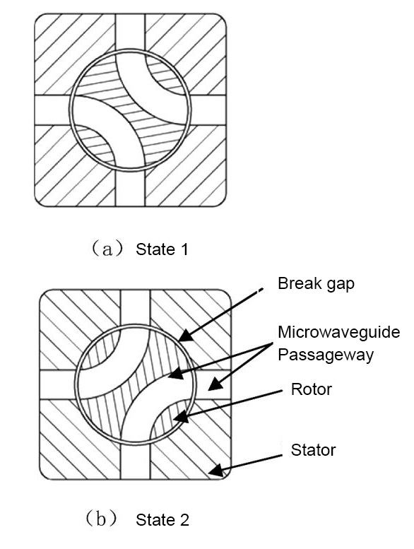
The microwave system of the waveguide switch includes two parts: a microwave rotor and a microwave stator. The microwave stator has 4 waveguide windows, which are evenly distributed around the stator; the microwave rotor contains 2 opposite 90° arc-shaped microwave channels.
The working principle of the waveguide switch is: the circuit control system applies an electric signal, the limited rotation angle motor generates a rotational torque and drives the microwave rotor to reciprocate between the 0° and 90° positions to realize the connection and switching between different waveguide windows, as shown in the figure 2.
2. Microwave parameter design
2.1 Design goals
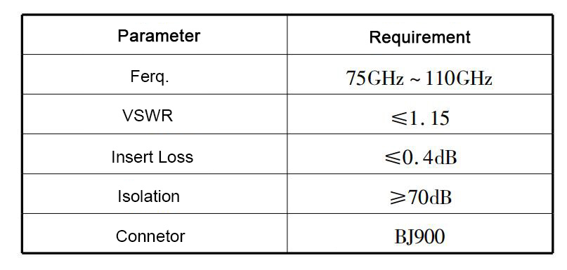
The specific design objectives of the microwave parameters of this product are shown in Table 1. It can be seen from Table 1 that the product has the characteristics of wide frequency band, low VSWR, small insertion loss, and high isolation.
2.2 Design of VSWR
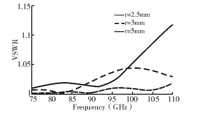
When the disconnection gap between the microwave rotor and the microwave stator is not considered, the microwave channel of the waveguide switch is composed of a straight waveguide at both ends and a 90° arc waveguide with the same cross-sectional size, and the voltage standing wave ratio increases with the radius of the curved waveguide And become smaller, and can be quantitatively calculated by equivalent circuit theory. The voltage standing wave ratio of the 90° WR10 arc waveguide calculated with this theory varies with its bending radius r as shown in Figure 3.
It can be seen from the figure that when the bending radius r≥3mm, a good match can be achieved between the straight waveguide and the arc waveguide, but considering the feasibility of processing and manufacturing, r=5mm is selected for this product, and the maximum VSWR at this time is 1.02, meeting the requirement of VSWR ≤ 1.15.
2.3 Insertion loss and isolation design
The waveguide switch developed in this paper is a rotary electromechanical switch, which relies on the microwave rotor to rotate in the microwave stator to switch the microwave channel. In order to ensure the switching flexibility, there is a certain gap between the microwave stator and the rotor, which we call the microwave channel disconnection gap hereinafter. The microwave channel breaks the gap to form a closed annular microwave signal leakage channel.
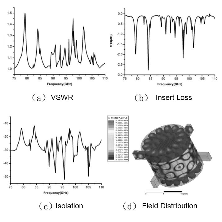
The microwave signal leakage channel can be regarded as a resonant cavity connected in parallel with the microwave channel of the waveguide switch. When the transmission signal is consistent with the resonant frequency of the resonant cavity, the resonance phenomenon shown in Figure 4 will appear. It can be seen from the figure that at the resonant frequency point The microwave performance of nearby waveguide switches will deteriorate dramatically.
Therefore, in order to realize high-quality transmission of microwave signals in a wider frequency range, it is necessary to prevent signal leakage.
In order to eliminate the resonance phenomenon, reduce the insertion loss, and improve the isolation, the most effective method is to realize electrical contact at the disconnection of the straight waveguide and the curved waveguide to reduce the leakage of electromagnetic waves. For low-frequency switches, it is common practice to set up vertical choke grooves on the microwave rotor, which can achieve a more ideal effect.
But for the W-band waveguide switch, where the frequency is high and the wavelength is high, only the way of loading the vertical choke groove is used, and the effect of preventing signal leakage is not ideal. In order to improve the choke effect, the method of simultaneously loading the annular choke groove and the vertical choke groove is adopted. An annular choke groove is set at the disconnection of the microwave channel to realize electrical contact; multiple vertical choke grooves are added on the cylindrical surface of the microwave rotor to further improve the isolation.
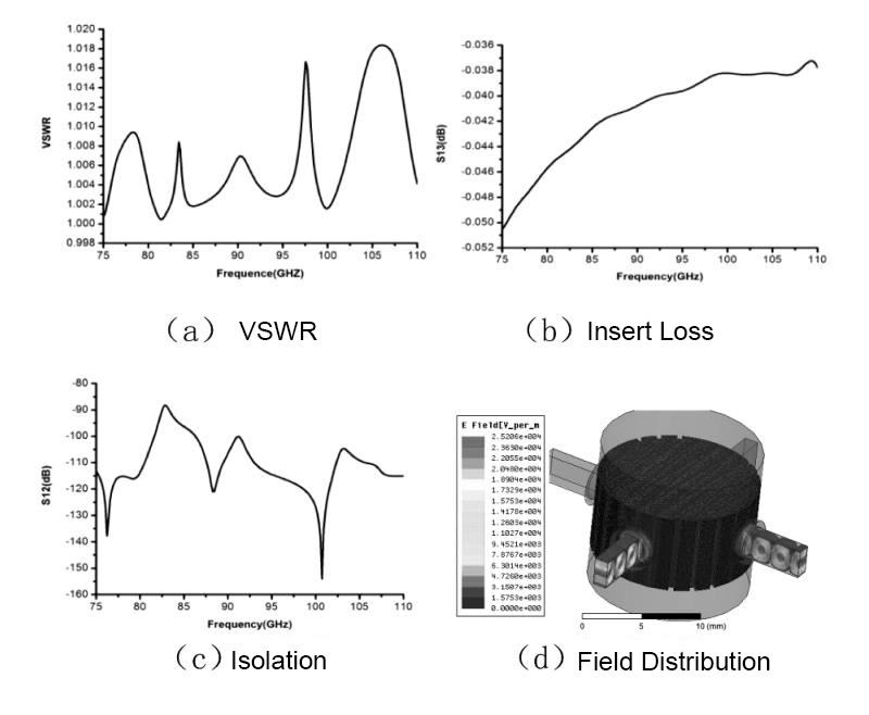
After considering the disconnection gap and choke groove of the microwave channel, the microwave signal transmission channel of the waveguide switch becomes more complicated, and its microwave performance cannot be accurately calculated by analytical methods. For this reason, the microwave system of the waveguide switch is simulated and optimized with HFSS software.
After the optimization is completed, the simulation results of the waveguide switch microwave system are shown in Figure 5. In the frequency range of 75gHz~110gHz, the VSWR is less than 1.02, the insertion loss is less than 0.06dB, and the isolation is greater than 85dB. The simulation results meet the design requirements. And have a larger margin.
2.4 Tolerance analysis
The purpose of tolerance analysis is to analyze the sensitivity of product performance indicators to structural parameters, find structural sensitive parameters and acceptable limit deviations, and provide support for product tolerance design.
In actual production, the size of the disconnection gap dr of the microwave channel, the degree of misalignment of the waveguide port, and the depth of the choke groove are affected by parts processing errors and assembly errors, and the microwave performance of the waveguide switch is relatively sensitive to it, so it is a better guide It is necessary for production to carry out tolerance analysis on the above parameters.
When analyzing the dislocation of the waveguide port, the dislocation amount of the narrow side of the waveguide port is represented by db, the dislocation amount of the wide side is represented by dΦ (the angle of the microwave rotor from the ideal position), and the depth of the choke groove is represented by dh.
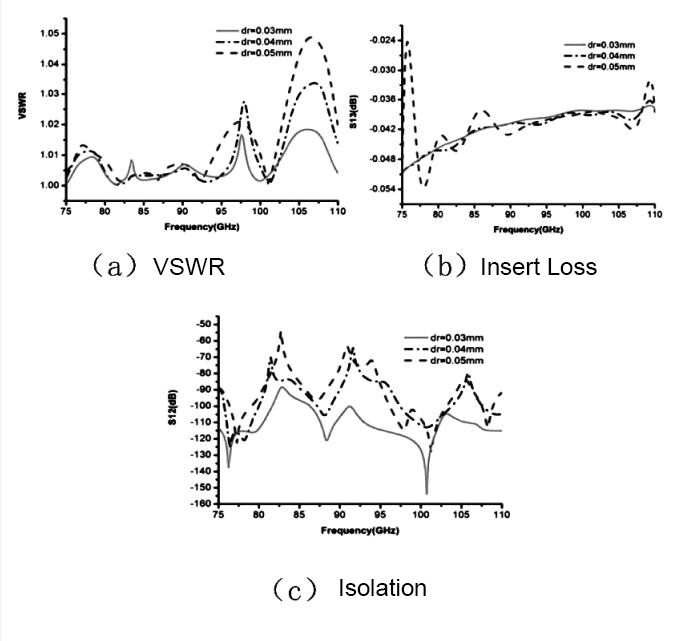
The variation of the microwave performance of the waveguide switch with the disconnection gap dr of the microwave channel is shown in Figure 6. It can be seen from the figure that in the range of 0~0.05mm, the change of dr has little influence on the insertion loss.
The VSWR at the high-frequency end deteriorates with the increase of dr, but it is within an acceptable range. The isolation degree decreases rapidly with the increase of dr. According to past development experience, in order to realize the isolation degree index of ≥ 70dB, dr ≤ 0.03mm.
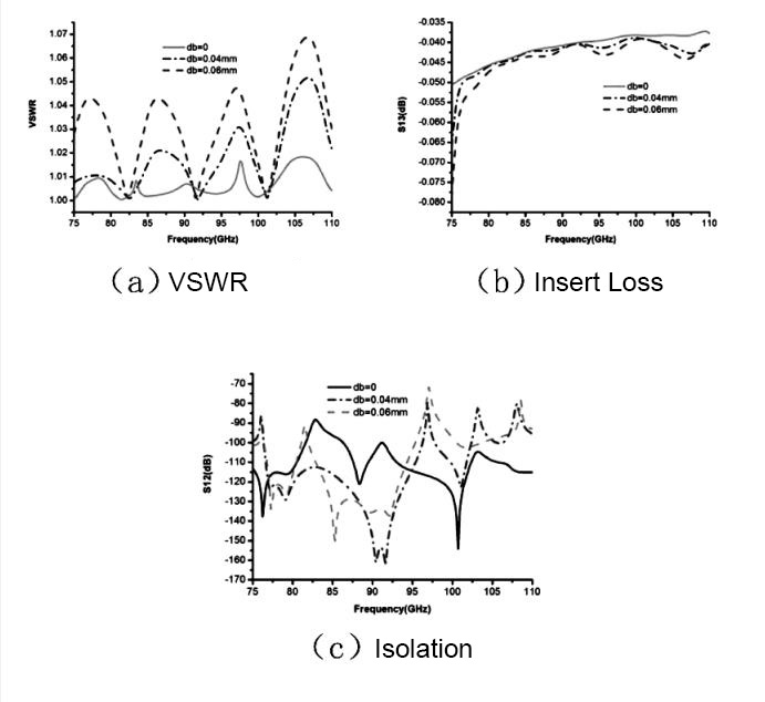
The influence of the misalignment of the narrow side of the waveguide port on the microwave performance of the waveguide switch is shown in Figure 7. It can be seen from the figure that in the range of 0~0.06mm, the insertion loss at the low frequency end increases with the increase of db; the voltage standing wave ratio and isolation deteriorate rapidly with the increase of db in the entire frequency range. In order to achieve low VSWR and high isolation index db≤0.04mm.
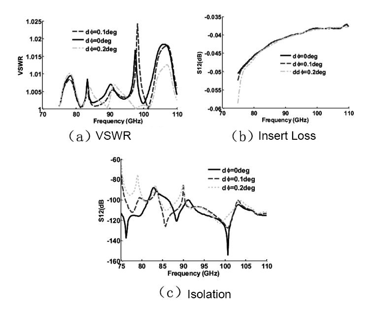
The influence of the misalignment of the wide side of the waveguide port on the microwave performance of the waveguide switch is shown in Figure 8. It can be seen from the figure that when dΦ changes in the range of 0deg~0.2deg, the influence on the voltage standing wave ratio is small.
The insertion loss at the low-frequency end increases with the increase of dΦ, and the isolation at the low-frequency end deteriorates rapidly with the increase of dΦ. In order to achieve the isolation index dΦ, it should be ≤0.2deg.
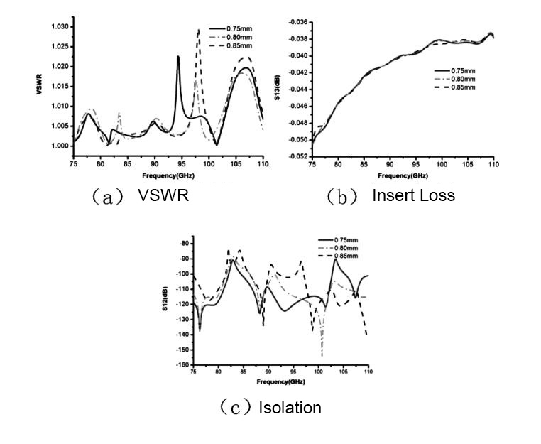
The influence of the choke groove depth dh on the microwave performance of the waveguide switch is shown in Fig. 9. It can be seen from the figure that when dh changes in the range of 0.75 mm to 0.85 mm, the VSWR and insertion loss are greatly affected. Small, although the impact on isolation is obvious, it is still within an acceptable range. Therefore, the depth range of the choke groove is: 0.75mm~0.85mm.
The results of the tolerance analysis show that in the design of the microwave system structure, the disconnection gap dr≤0.03mm, the misalignment of the narrow side of the waveguide mouth db≤0.04mm, the misalignment of the wide side of the waveguide mouth dΦ should be ≤0.2deg, and the depth of the choke groove should be controlled at : 0.75mm~0.85mm.
3. Measured results
According to the tolerance analysis results, in order to ensure the flexible rotation of the switch and realize the microwave performance index, during the production of this product, the disconnection gap dr of the microwave channel is controlled within the range of 0.015mm~0.03mm, and the misalignment db of the narrow side of the waveguide port is controlled within 0mm In the range of ~0.04mm, the misalignment dΦ of the waveguide port width is controlled in the range of 0deg~0.2deg, and the depth dh of the choke groove is controlled in the range of 0.75mm~0.85mm.
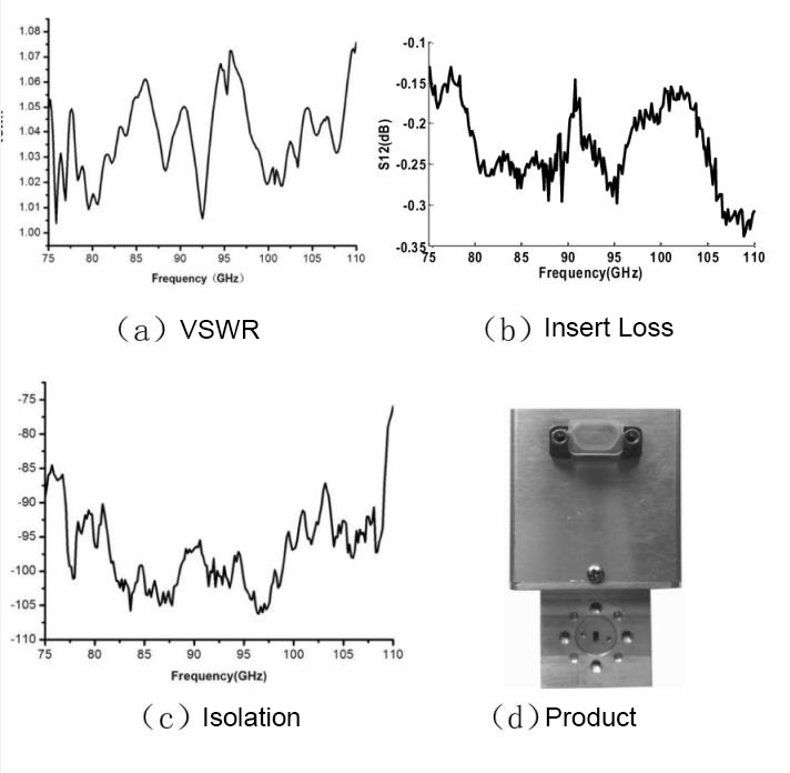
Product photos and specific measured curves are shown in Figure 10. It can be seen from the figure that in the frequency range of 75gHz~110gHz, the VSWR of the waveguide switch is <1.08, the insertion loss is <0.35, and the isolation is >76dB, fully meeting the design goals.