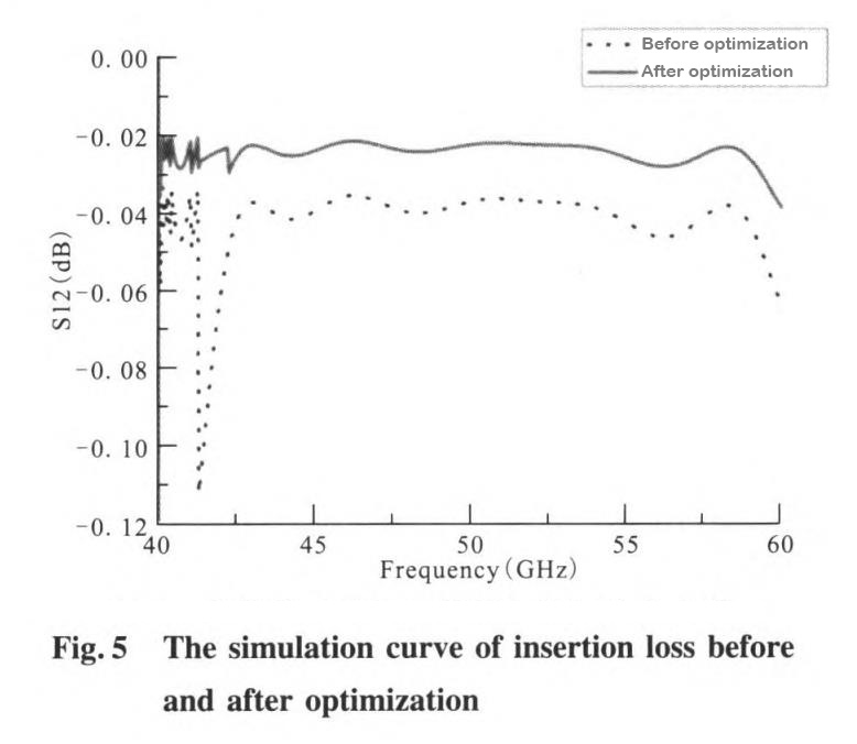
U-band electromechanical waveguide switch’s principle and design
At present, with the development of 5G communication, the frequency band around 40GHz to 60GHz has attracted attention from all sides. Theoretically speaking, if the system capacity is further improved, it is imperative to increase the bandwidth. However, the crowded wireless spectrum allocation below 10GHz has ruled out this possibility, and new spectrum resources need to be opened up to realize ultra-high-speed wireless data transmission. The U-band is near the extreme value of atmospheric attenuation and is used in systems such as secure communication, inter-satellite link communication, interference and anti-jamming, so it is of great significance to study various microwave systems in the U-band.
Communication services, especially secure communications, have more and more demands on U-band, and the application of U-band is becoming more and more mature. In order to convert microwave signals between different channels, it is inevitable to use microwave switches.
According to different types of transmission lines, electromechanical microwave switches are divided into electromechanical coaxial switches and electromechanical waveguide switches. Generally, the electromechanical coaxial switch has a wide frequency band, but the voltage standing wave is relatively high and the insertion loss is relatively large, which cannot meet the needs of precision electronic systems. Electromechanical waveguide switches have attracted more and more attention from engineers and system designers due to their low VSWR, small insertion loss, and high power handling.
The number of channels of the switch rotor is different, and the functions realized by the waveguide switch are different. The waveguide switch can be divided into a C-type switch and an R-type switch. The C-type waveguide switch has two curved channels, which can complete the transformation of two working states, and the switching form is double-pole double-throw. In communication systems, C-type waveguide switches are widely used.
1. Structure and principle
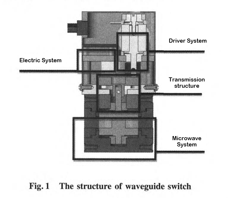
The C-type waveguide switch contains two microwave channels, which can realize the function of double-pole double-throw switch. The waveguide switch is divided into four parts: drive part, circuit system, transmission structure and microwave system, as shown in Figure 1. The function of the drive system is to convert the electric energy of the control signal into mechanical energy, provide power for the state switching of the waveguide switch, and keep the switch in the original position when there is no external excitation; the function of the circuit system is to realize the excitation control of the motor and eliminate the coil. Inverse peak voltage and provide switch status information; the function of the transmission structure is to connect the motor rotor and the microwave rotor, and transmit the motor rotational torque to the microwave rotor, thereby driving the switching of the microwave channel; the microwave system affects the microwave performance index of the waveguide switch, and its main To complete the high-quality transmission of microwave signals, it is the final executor of waveguide switch signal transmission.
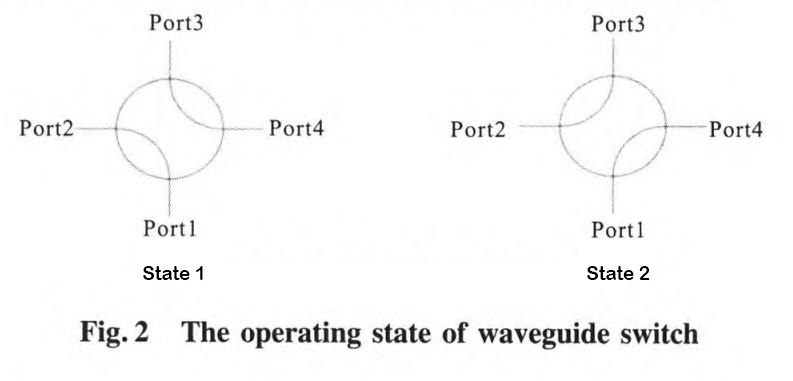
The working principle of the C-type waveguide switch is that the electric signal is applied through the circuit system, and the driving part generates switching power. Through the transmission structure, the microwave rotor is driven to move back and forth between the two positions of -45° and 45°, and the two channels are switched to realize double poles. The double throw function is shown in Figure 2.
2. Microwave parameters
The main microwave parameters of waveguide switches are VSWR, insertion loss and isolation. It can be seen from the microwave parameter design goals that it has the characteristics of wide frequency band, low standing wave, small insertion loss, and high isolation.
2.1 Low VSWR
When the disconnection gap between the microwave rotor and the microwave stator is not considered, the microwave channel of the waveguide switch is composed of a microwave fixed-production straight waveguide and a 90° arc waveguide of the microwave rotor, and the voltage standing wave ratio increases with the bending of the microwave rotor arc waveguide Decreases as the radius increases, and can be calculated using equivalent circuit theory.
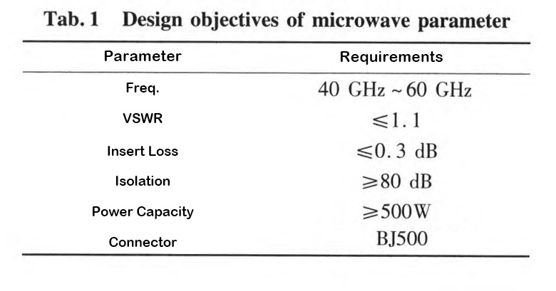
Through the HFSS software simulation, the simulation results of the VSWR of the 90° BJ500 arc waveguide with the change of the bending radius r are shown in Figure 3. It can be seen from the figure that the larger the bending radius, the better the matching between the straight waveguide and the curved channel can be achieved. Considering the feasibility of processing and manufacturing, this product chooses r = 5mm. At this time, the maximum VSWR is 1.05, which meets the design requirement that the VSWR is less than or equal to 1.1.
2.2 Small insertion loss
Waveguide switches are mainly used in multi-channel microwave transceiver systems, and the small insertion loss index is conducive to improving the dynamic range of receiving equipment, thereby improving the sensitivity of the equipment.
However, the waveguide switch developed in this paper is a rotary electromechanical waveguide switch. The switching of the microwave channel is realized by the rotation of the microwave rotor in the microwave stator.
Therefore, in order to ensure the flexible rotation of the microwave rotor, there is a certain gap between the microwave rotor and the microwave stator. Hereinafter referred to as channel gap (set as d).
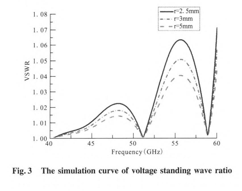
Due to the existence of channel gaps, microwave signal leakage is inevitable. The channel gap can be regarded as a resonant cavity connected in parallel with the waveguide channel. When the resonant frequency in the resonant cavity is consistent with the frequency of the transmission signal, the resonance phenomenon shown in Figure 4 appears. From the simulation results, it can be seen that the microwave performance of the waveguide switch is close to the resonant frequency point. Rapid deterioration Therefore, the design focus of this product is how to optimize the channel gap to prevent signal leakage.
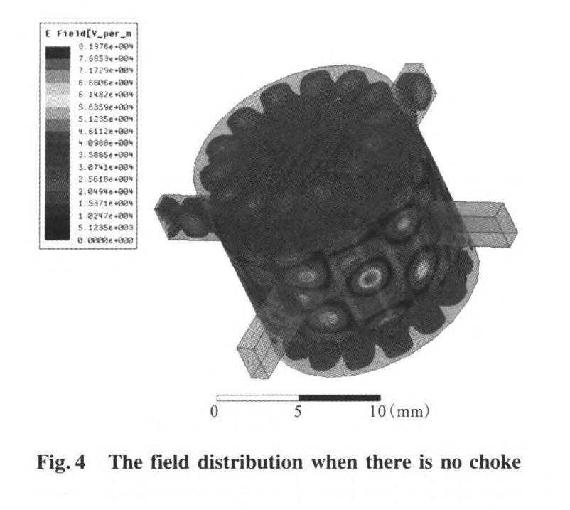
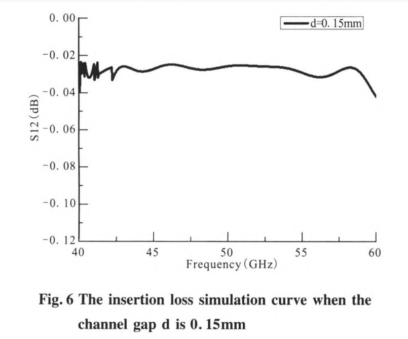
Through the optimization function of the HFSS simulation software, the channel gap of the microwave system of the waveguide switch is simulated and optimized. The simulation results of the insertion loss of the microwave system of the waveguide switch before and after optimization are shown in Figure 5. It can be seen from the figure that before optimization (d = 0.03mm), the insertion loss of the switch is relatively large, and at around 41.5GHz, the insertion loss suddenly increases. After optimization (d=0.0147mm), the insertion loss index is good, less than 0.04dB, and the curve is relatively smooth. Reach the design target requirements, and there is a large margin. Considering the feasibility of processing, this product selects the channel gap as d = 0.15mm, and conducts simulation verification, as shown in Figure 6. It can be seen from Figure 6 that when the channel d = 0.15mm, the maximum insertion loss is 0 045dB, Meet the design requirements of insertion loss near 0 3dB.
2.3 High isolation
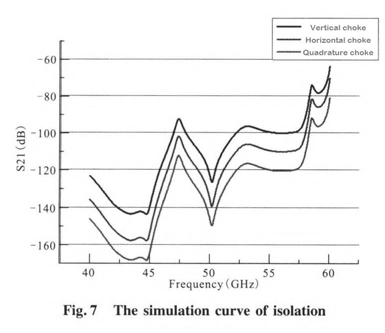
Isolation is an indicator of signal interference between microwave channels. The traditional method to improve isolation is to set choke grooves on the microwave rotor, but for U-band waveguide switches, only the method of setting one-way choke grooves is not enough to contain signal leakage, as shown in Figure 7, the indicators cannot meet the requirements .
In order to improve the choke effect, this product adopts the method of setting orthogonal choke slots. Orthogonal choke slots are set in the channel gap to realize the electrical contact between the microwave stator and the microwave rotor; meanwhile, multiple unidirectional choke slots are set on the cylindrical surface of the microwave rotor to further improve the isolation. Through HFSS simulation software modeling and calculation, the U-band (40GHz6) waveguide switch microwave system isolation simulation results are shown in Figure 7. When the design scheme is an orthogonal choke slot, the full-band isolation of the switch is greater than 80dB, which meets the design target requirements.
2.4 Power capacity simulation
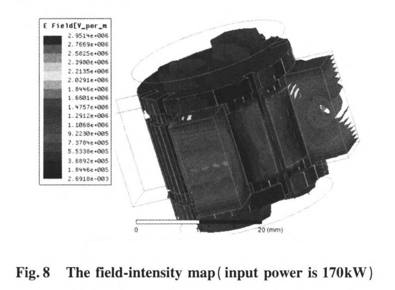
The microwave channel of the waveguide switch is filled with air, and the peak power capacity assessment is the ability of the air in the microwave channel to resist electrical breakdown. The electric field breakdown field strength of air at normal pressure is 3 x 10^6V/m. Through the HF-SS simulation analysis, when the input power is 170kW, the electric field intensity distribution in the microwave channel is shown in Figure 8. It can be seen from the figure that the highest value of the electric field intensity at this time is 2.95 x 10^6 V/m , is smaller than the breakdown field strength of air at normal pressure, so the peak power capacity of the switch at normal pressure is 270kW, which meets the safety performance requirements of the switch.
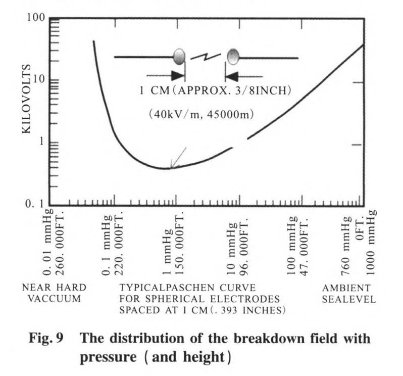
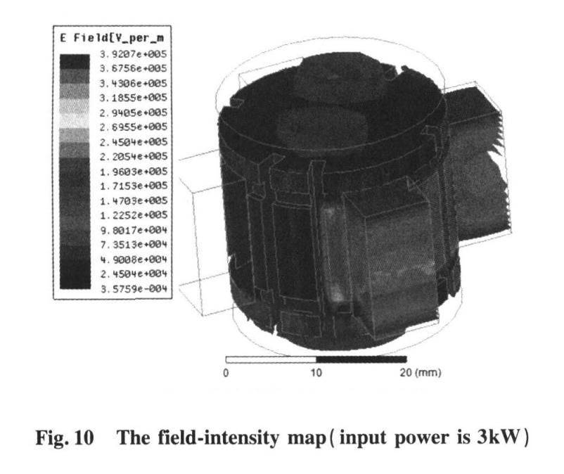
The air breakdown field strength varies with the pressure, and the relationship is shown in Figure 9. It can be seen from Figure 9 that the lowest point of the breakdown field strength is near (40kV/m , 45000m), so the power capacity of the waveguide switch under low pressure can be obtained. When the input power is 3kW, the distribution of electric field intensity in the microwave channel is shown in Figure 10. It can be seen from the figure that when the input power is 3kW, the highest value of the electric field intensity is 39.2kV/m, which is smaller than the lowest breakdown field of air under low pressure Strong 40kV/m, indicating that the peak power capacity of the switch under low air pressure is 23kW, which is much higher than the initial design index requirements, and meets the current use conditions in the communication system:
3. Measured results
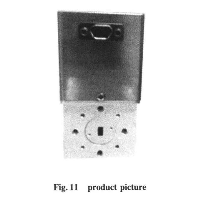
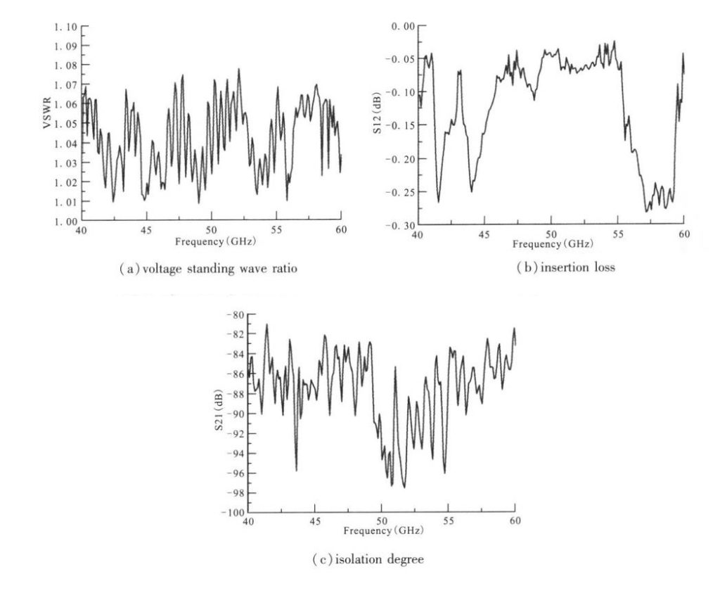
Through the design of the waveguide switch microwave system, especially the optimization of the microwave channel gap, the microwave gap is designed to be between 0.02mm-0.04mm. The manufactured physical product is shown in Figure 11, and the measured curve of the product is shown in Figure 12. The actual measurement results show that in the frequency range of 40GHz-60GHz, the waveguide switch voltage standing wave ratio is <1.08, the insertion loss is <0.3dB, and the isolation is >80dB, fully meeting the design requirements. Of course, we also need professional CNC machining service providers to turn our paper design drawings into actual products.