How to solve RF switches’ heat dissipation problem?
RF switch, also known as microwave switch, realizes the function of controlling microwave signal channel conversion. An RF (radio frequency) and microwave switch is a device to route high-frequency signals through the transmission path. RF and microwave switches are widely used in microwave test systems. Signal routing between the instrument and the device under test (DUT). By combining switches into a switch matrix system, signals from multiple instruments can be routed to a single or multiple DUTs, which enables multiple tests to be performed under the same setup without frequent connections and disconnections, and the entire test process Can be automated, increasing throughput in high-volume production environments.
Under this condition, the existing high-speed radio frequency switch has a high internal radio frequency rate and generates more heat, so it is urgent to improve its heat dissipation effect. However, the existing high-speed radio frequency switch has a poor heat dissipation effect and cannot effectively conduct heat to the outside. The surface of the high-speed radio frequency switch housing is set horizontally, and the liquid cannot be quickly guided. The liquid stays on the cover for a long time and will penetrate into the interior of the housing, thereby damaging the radio frequency switch.
A high-speed radio frequency switch with adjustable speed is introduced here; it includes the terminal part, the inner convex seat, the first slope area and the second slope area, and the first slope area and the liquid guide groove area are arranged on both sides of the surface of the panel cover. Both ends of the first slope area are provided with a second slope area, and the top of the first slope area is fixed with multiple sets of heat dissipation components;
The first slope area and the second slope area provided on the panel cover of the new radio frequency switch can quickly conduct liquid on the surface of the cover plate, preventing the liquid from staying for a long time and penetrating into the inside of the radio frequency switch, damaging components, and at the same time There are symmetrically arranged heat sinks on the first slope area, and heat dissipation air grooves are formed inside the paired heat sinks. On the one hand, it can effectively dissipate heat, and on the other hand, it can adhere to the surface of the cover plate after the liquid is conducted on the surface of the cover plate. The residual liquid is quickly dried, and the design of the inner convex seat in the middle of the heat sink can increase the wind speed, thereby enhancing the heat dissipation capacity of the middle part of the heat dissipation air groove.
The radio frequency switch is composed of a terminal part 1 and a radio frequency terminal part 3. In specific use, the two are fixedly installed through threads, and the panel cover plate 4 of the radio frequency terminal part 3 is provided with a first slope area 9 and a second Two slope areas 11;
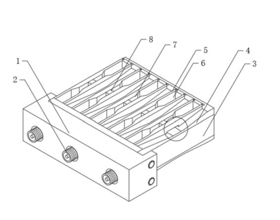
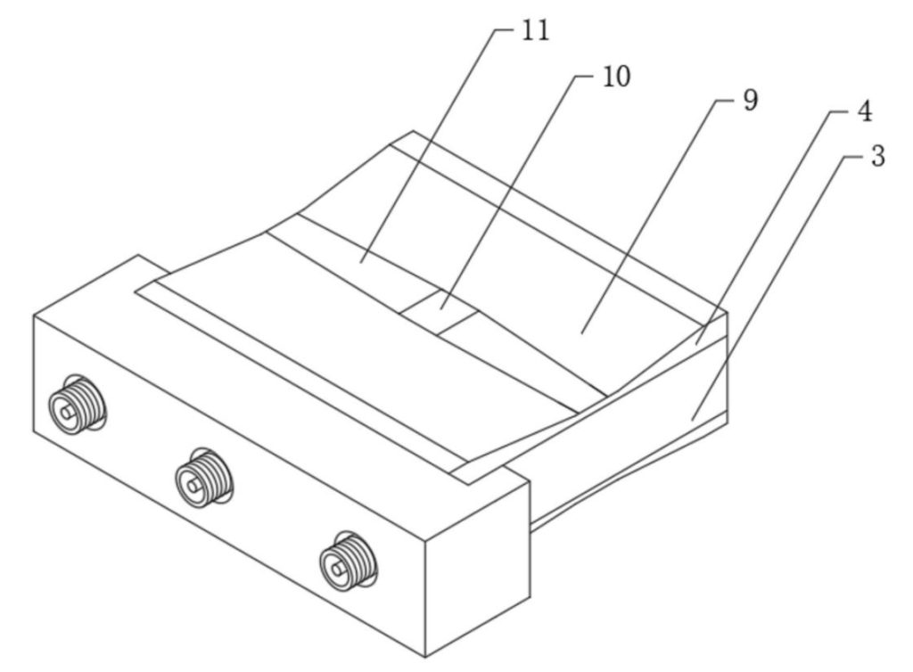
When there is liquid on the surface of the panel cover 4, the liquid can be quickly guided on the surface of the panel cover 4 to prevent the liquid from staying for a long time and then penetrating into the RF switch and damaging its internal components;
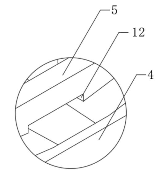
At the same time, symmetrically arranged heat sinks 5 are arranged on the first slope area 9, and heat dissipation air grooves 6 are formed inside the pair of heat sinks 5. On the one hand, the panel cover plate 4 can effectively dissipate heat, and the heat conducted from the inside of the radio frequency end 3 quickly dissipates in the air;
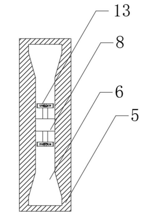
On the other hand, after the liquid is conducted on the surface of the panel cover plate 4, the residual liquid adhering to the surface of the cover plate can be quickly air-dried, and the inner convex seat 7 in the middle of the heat sink 5 is designed;
Due to the reduction of the inner diameter of the inner convex seat 7 of the heat dissipation air groove 6, the wind speed is enhanced, thereby enhancing the heat dissipation capacity of the middle part of the heat dissipation air groove 6, and at the maximum wind speed inside the heat dissipation air groove 6, a miniature heat dissipation fan 13 is also provided to further enhance the cooling effect. its cooling capacity.