Broadband DPDT coaxial switch principle and design idea
With the rapid development of microwave technology, coaxial switches, as passive microwave devices that can transmit and switch radio frequency signals almost without distortion, have received more and more attention. The double-pole double-throw coaxial switch is also called a changeover switch. It has the advantages of wide applicable frequency, low loss and good repeatability. It has been widely used in automatic test instruments such as microwave synthesis signal sources, vector network analysis instruments, and spectrum analyzers. Provides reliable conversion for routing signals in instruments and systems. In this paper, a coaxial switch can be used at DC-26.5GHz, and the loss in the passband is better than 1dB.
1. Structure and working principle
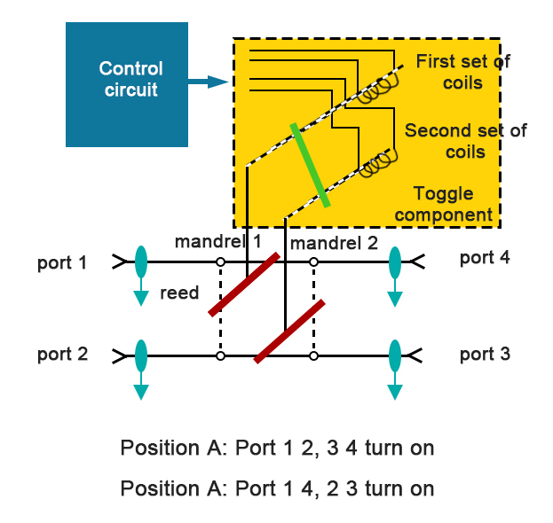
The principle block diagram of the coaxial switch is shown in Figure 1. The switch is composed of a control circuit, an electromagnetic drive component, a microwave signal transmission path, a casing, a cover plate and other components. The switch control circuit controls whether there is current flowing in the coil of the electromagnetic drive component. Once the current flows through the coil, the coil generates a magnetic field, and the generated electromagnetic force pushes the armature block to move, and then drives the transmission reed to move through the ejector rod, making the microwave signal The input terminal is connected or disconnected from the output terminal to realize the switching between the two working states of Position A or Position B.
2. Shielded stripline transmission line structure
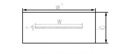
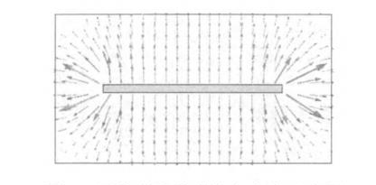
The stripline can be regarded as the evolution of the coaxial line, the inner and outer conductors of the coaxial line are turned into rectangles, and the narrow side extends to infinity to become a stripline; if two metal walls are used to cut off the narrow side , call it a shielded stripline, the shielded stripline structure diagram and the schematic diagram of the power line are shown in Figure 2 and Figure 3. Shielded stripline transmission lines are now widely used in various microwave mechanical switches, microwave step attenuators and other microwave components.
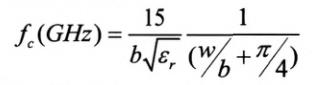
Cutoff frequency for shielded stripline:
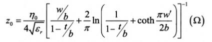
Shielded stripline impedance:
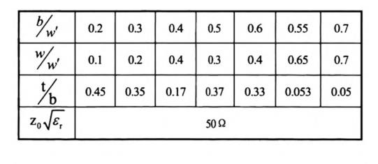
The initial values of the dimensions of the shielded stripline, the cavity, and the intermediate conductor are given in the literature, as shown in Table 1. According to the initial value in Table 1, combined with HFSS, it is simulated and optimized. We choose: b/w’=0.55, w/w’=0.65, t/b=0.053, εr=1, reed thickness t=0.06mm. Using HFSS modeling, it can be calculated that the port impedance is 49.75ohm, and the cut-off frequency fc=64.45GHz of this structure can meet the use of the transfer switch in this project.
3. Test results
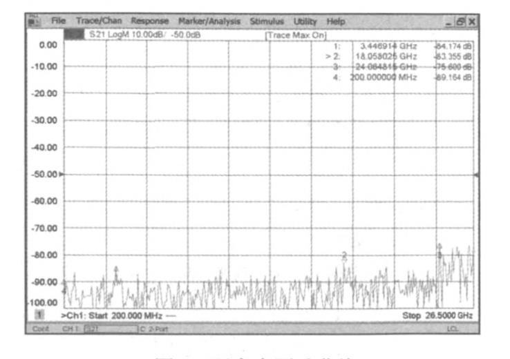
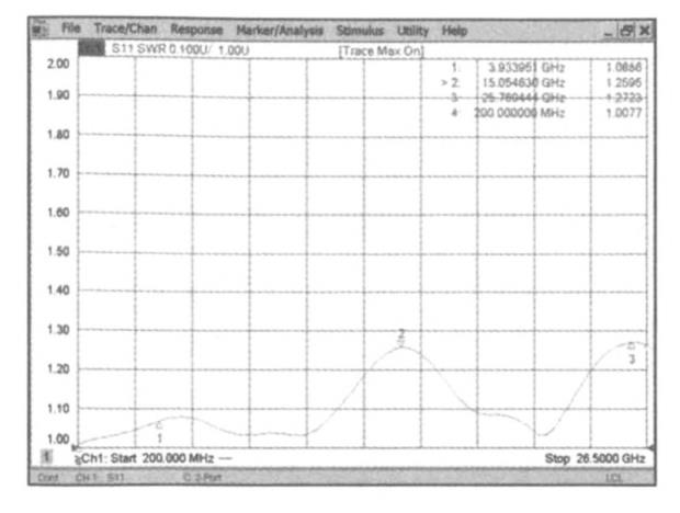
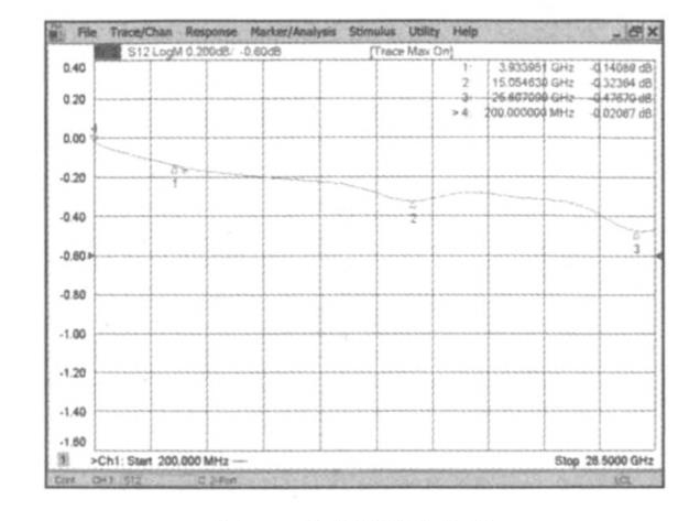
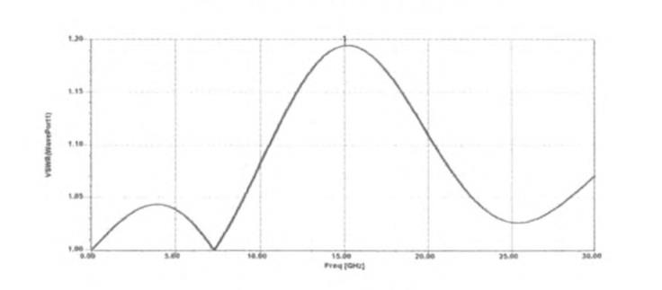
The switch can realize technical characteristics such as frequency bandwidth, low loss, and high isolation within the broadband range of DC to 26.5GHz. The straight-through insertion loss is better than 0.5dB in the full passband range, the port VSWR is less than 1.3, and the isolation is better than 70dB. Figure 7, Figure 8, and Figure 9 respectively show the physical test curves of isolation, standing wave ratio, and insertion loss, which are in good agreement with the simulation structure and meet the actual use requirements.
The key to the design of precision coaxial connectors lies in the design of the medium support. At the medium support, due to the loading of the medium and the sudden change in the size of the inner and outer conductors, it will cause impedance discontinuity and easily stimulate non-transmission|high-order modes, which will deteriorate the coaxial connector index. For this reason, the effective dielectric constant can be reduced by axially punching or digging grooves on both sides of the dielectric support, and the coplanar compensation for the capacitive effect caused by the discontinuous size can be performed.
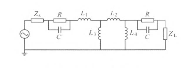
In order to be used in the wide frequency range of DC to 26.5GHz, the coaxial switch must reduce the discontinuity in the microwave transmission path, which is mainly caused by structural discontinuity. For each discontinuity (such as contact area, wedge size, small hole size, etc.), compensation measures are taken in the design. The contact area is equivalent to the contact capacitance C and the contact resistance R: when there is a step change in the stripline, the distribution parameter can be equivalent to an inductance [8], and the small round hole in the center of the moving reed can be equivalent to an L2 The inductance network composed of ~ L4, so the equivalent circuit of the discontinuous structure from coaxial to shielded stripline transition can be given as shown in Figure 4. In the simulation calculation, the area where the high-order mode field exists should be minimized, and the cut-off frequency of the high-order mode should be outside the operating frequency.
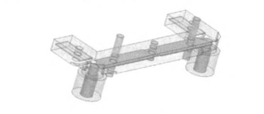
The HFSS simulation model and simulation results of the coaxial to shielded stripline structure are shown in Figure 5 and Figure 6. Here we choose the aperture as 0.3mm and the diameter of the dielectric column as 0.33mm.
3. Test results
The switch can realize technical characteristics such as frequency bandwidth, low loss, and high isolation within the broadband range of DC to 26.5GHz. The straight-through insertion loss is better than 0.5dB in the full passband range, the port VSWR is less than 1.3, and the isolation is better than 70dB. Figure 7, Figure 8, and Figure 9 respectively show the physical test curves of isolation, standing wave ratio, and insertion loss, which are in good agreement with the simulation structure and meet the actual use requirements.