A More Excellent Random Switching Microwave Coaxial Switch
We know that microwave coaxial switches can be divided into random switching and sequential switching according to the switching mode.
The random switching microwave switch means that the microwave switch can switch between multiple working states arbitrarily. Therefore, for the drive motor, multiple independent wire packages are required to drive each working state. At the same time, multiple control circuits and multiple Instructions control each work state. Multiple independent drive wire packages increase the weight of the drive motor and thus the weight of the entire microwave switch; multi-channel control circuits require multiple diodes, reed switches, and other components, and the introduction of multiple components reduces the weight of the entire microwave switch. reliability.
Therefore, the existing random switching coaxial switch has disadvantages such as large volume and weight, low reliability, and many control instructions.
Therefore, to overcome the above-mentioned defects, a sequential microwave coaxial switch and a method of use are provided. The microwave coaxial switch includes a sequential driving device, a radio frequency device, and a sequential telemetry device. In the sequential driving device, the locking structure utilizes the upper magnetic steel The attraction and repulsion between the magnetic steel group and the lower magnetic steel group realizes the sequential switching of three stable states during the rotation of the motor rotor, and then drives the contact piece to conduct the corresponding radio frequency channel of the radio frequency device, realizing the working state of the radio frequency device At the same time, the sequential telemetry device conducts the corresponding reed switch along with the motor rotor, realizing the feedback of the working status of the radio frequency device to the external circuit.
The following technical solutions are provided: a sequential microwave coaxial switch, including a sequential driving device, a radio frequency device, and a sequential telemetry device;
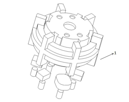
The sequential driving device includes a stator copper coil and a locking structure; the inner surface of the stator and the outer surface of the rotor is provided with teeth, the copper coil is embedded inside the stator, and the rotor is located inside the copper coil and can rotate coaxially relative to the stator;
The locking structure includes a contact piece assembly, a turntable, an upper magnet group and a lower magnet group; the turntable is fixedly installed on the rotor, the upper magnet group is installed on the lower surface of the turntable, and the lower magnet group is located below the upper magnet group; the lower layer The magnetic steel group includes 3 pairs of lower layer magnetic steels arranged in a circular ring A with the same polarity, and the connection line of each pair of lower layer magnetic steels passes through the center of the circular ring A; the contact piece assembly includes a The contact piece is used to conduct the corresponding radio frequency channel in the radio frequency device; the upper layer magnetic steel group includes 3 pairs of upper layer magnetic steel arranged in a circular ring B, and the connection line of each pair of upper layer magnetic steel passes through the ring In the center of shape B, among the 3 pairs of upper magnets, 1 pair of upper magnets and the lower magnets repel each other, which is recorded as the upper repelling magnets, and 2 pairs of upper magnets and the lower magnets attract each other, which is recorded as the upper magnets steel;
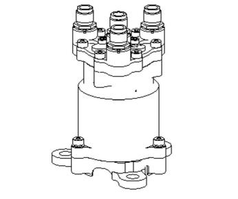
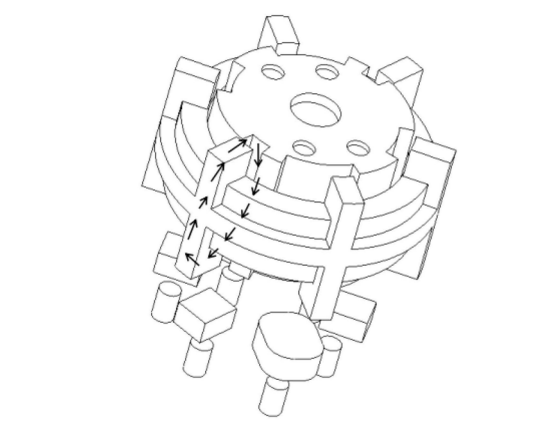
The turntable rotates synchronously with the rotor, driving the upper magnetic steel to rotate. When the sequential drive device is in a stable state, the teeth of the stator and the rotor are in a non-aligned state, and a pair of upper repelling magnetic steel is located at the position corresponding to a pair of lower magnetic steel. The repulsive force between the upper repelling magnet and the lower magnet makes the lower magnet move downward and then drives the contact piece to conduct the corresponding radio frequency channel. When the copper coil is powered on, the rotor continues to rotate to the teeth of the stator under the action of the electromagnetic field. Align with the teeth of the rotor (the edges of the teeth are aligned), the sequential drive device is in the middle balance state, after the copper coil is powered off, the repulsive force between the upper repelling magnet and the adjacent lower magnet makes the rotor continue to rotate to the upper The repulsive magnetic steel corresponds to the next pair of lower layer magnetic steels, and the sequential driving device reaches the next stable state; the specific details will not be detailed one by one. Here you can see the shape of its structure in the picture below.
Although it is a little more complicated in structure, it may increase the processing difficulty and cost, but we still want to pay tribute to our inventor, this sequential coaxial switch is the realization of stable, reliable and efficient sequential switching Great progress has been achieved, and it has broad application prospects in the field of microwave switches. We hope that our designers can go to the next level and design better products.