Research on a new ultra-small conductive slip ring
As a key electrical transmission device that transmits power and control signals from the fixed end to the rotating end, the conductive slip ring can be used in the rapid development period of weaponry, aviation, weaponry, high-end industrial control, new energy development, and other industries. It provides good development opportunities and broad market prospects for conductive slip rings. With the rapid improvement of the scientific and technological capabilities of various countries in recent years, all kinds of military and high-end industrial equipment are developing in the direction of miniaturization and integration. The use of miniaturization requires that although the market prospect of ultra-small conductive slip rings is good and the demand is large, it is very difficult to realize it.
For ultra-small conductive slip rings, it is extremely difficult to achieve mutual insulation and mutual shielding between multiple current or signal channels in a small space. Therefore, achieving reliable mutual insulation between multiple conductive rings on the conductive slip ring has become a key technical difficulty.
This paper proposes an ultra-small precision conductive slip ring, which successfully solves the problems of easy debonding between the conductive ring and the insulating sheet and poor product reliability when manufacturing ultra-small conductive slip rings with lamination combined bonding mode, and realizes two The conductive loops are not only insulated from each other, but also achieve reliable connection, and the glue layer will not fall off, which improves the environmental adaptability and working reliability of the product.
1 Working principle
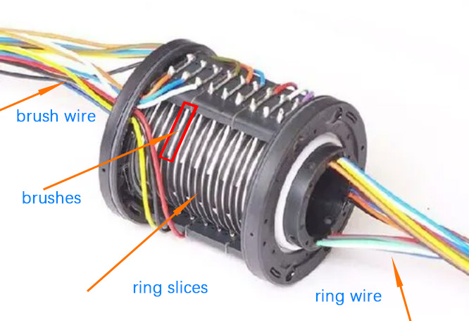
At present, the formation of general conductive slip ring rotating components is mainly realized through the lamination combination bonding process, that is, the lamination combination structure is adopted, the insulating sheet is sandwiched between every two copper ring sheets, and the insulating sheet and the copper ring sheet are glued together. Form a lamination bonding process. The biggest advantage of using this manufacturing process is that the insulation between each conductive ring is realized by the insulating sheet with good insulation performance placed between the conductive rings, so the insulation performance between any two conductive rings can be reliably guaranteed. But the main problem is that the insulating sheet and the copper sheet of the conductive ring are glued together by adhesive glue. When the laminations are combined, the thickness of the adhesive layer between the laminations is likely to be seriously uneven due to inconsistent lamination pressure. , There may even be glue loss in some places, which is especially obvious on ultra-small conductive slip rings. Therefore, the ultra-small conductive slip ring assembly manufactured by this process is subject to vibration for a long time, or under the working conditions of the large temperature differences and frequent temperature changes, the adhesive layer is prone to peeling off, which will affect the reliability of the conductive slip ring.
The rotating component of the core component of the conductive slip ring involved in this paper abandons the conventional lamination combination of rings, insulating sheets, and rings in terms of structural design, and adopts a single convex ring stack. The resin is poured and solidified, and finally the rotating assembly is shaped by finishing turning. This rotating assembly forming technology without insulating sheets can make the space position of the rings arranged more symmetrically, and the epoxy insulating layer between the rings is filled densely. , Uniform, thus guaranteeing the technical performance of the ultra-small conductive slip ring to a great extent.
The rotating assembly includes a rotating shaft, a rotating flange, a convex ring piece, and a ring lead wire, wherein the rotating shaft is a hollow structure, and its technical scheme is as follows.
First lead out the ring leads from the inner wall of the convex ring piece by welding, then insert the convex ring piece into the rotating shaft, the ring lead wire will be drawn out through the hollow inner hole of the rotating shaft, and then press the rotating flange tightly to each convex ring The rotating flange and the rotating shaft are fixed together by screws, and finally epoxy resin glue is poured from the hollow inner hole of the rotating shaft, and the epoxy resin glue will fill the inner hole of the rotating shaft and the gap between the convex ring pieces. At all the gaps, the epoxy resin glue is cured, and then the protruding part of the end of the convex ring piece is completely turned off in the diameter direction with a turning tool to ensure that there is no short circuit between the ring pieces, and then the outer wall of the ring piece Car out the inverted trapezoidal groove, and then electroplate the ring piece to complete the processing of the rotating component.
2 Structural Design
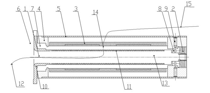
It can be seen from Figure 3 that the ultra-small, multi-loop precision conductive slip ring mainly includes: rotating assembly 1, lock nut 2, brush assembly 3, integrated bracket 4, outer cover 5, cover plate 6, large precision bearing 7, small Precision bearing 8, Phillips countersunk head screw 9, wherein the rotating assembly 1 is composed of a rotating shaft 10, a ring piece 11, a ring lead wire 12, and epoxy resin 13, and a brush wire 14 is fixed on the brush assembly 3. The lower end forms frictional contact with the outer surface of the ring piece 11 , and the upper end of the brush wire 14 leads out the brush lead wire 15 .
Its assembly process is introduced as follows.
The cylindrical integrated bracket 4 has a large inner diameter at the left end and a small inner diameter at the right end, and bearing positions are respectively provided at the left and right ends of the integrated bracket 4 .
A large precision bearing 7 is installed on the left end of the integral support 4, and a small precision bearing 8 is installed on the right end of the integral support 4.
A plurality of ring pieces 11 are fixed on the rotating component 1, and each ring piece 11 leads out a ring lead wire 12 passing through the inner hole of the rotating component 1 as a lead wire at the rotating end of the slip ring.
The inner hole of the rotating assembly 1 is filled with epoxy resin glue 13 for sealing and insulation;
The left end and the right end of the rotating assembly 1 pass through and are sleeved in the large precision bearing 7 and the small precision bearing 8 respectively. A brush assembly 3 is installed on the outer wall of the integrated bracket 4, and a brush wire 14 is fixed on the brush assembly 3;
The lower end of the brush wire 14 forms frictional contact with the outer surface of the ring piece 11; the upper end of the brush wire 14 leads to the brush lead 15 as the lead wire at the fixed end of the slip ring.
The outer cover 5 wraps the outer circle of the integrated support 4 and is fixed thereon by the Phillips countersunk head screws 9, so that the outer cover 5 cannot rotate on the integrated support 4.
The lock nut 2 connects the rotating assembly 1, the integrated support 4 and the outer cover 5 as a whole by pressing the small precision bearing 8.
The rotating component includes the main shaft and its ring pieces, ring leads and other parts that rotate with the shaft. The forming technology of the rotating component determines the key technical indicators such as the performance and reliability of the entire conductive slip ring.
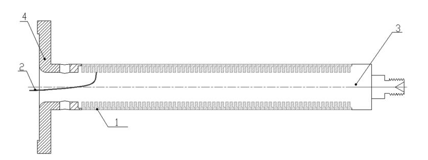
The schematic diagram of the structure of the ultra-small conductive slip ring rotating assembly to be realized in this project is shown in Figure 4.
In Figure 4, the rotating assembly includes a rotating shaft 3, a rotating flange 4, a convex ring piece 1, and a ring lead 2, wherein the rotating shaft 3 is a hollow structure, and the assembly process of the rotating assembly adopts an integrated process technology, which is now introduced as follows.
Lead the ring lead 2 from the inner wall of the convex ring piece 1 by welding, then insert the convex ring piece 1 into the rotation shaft 3 from left to right, and the ring lead wire 2 will be drawn out from the left end through the hollow inner hole of the rotation shaft 3 , and then press the rotating flange 4 from the left end to each convex ring piece 1, fix the rotating flange 4 and the rotating shaft 3 together by screws, and finally pour epoxy resin glue from the hollow inner hole of the rotating shaft 3 at the left end, The epoxy resin glue will be filled with the inner hole of the rotating shaft 3 and all the gaps between the convex ring pieces 1, and the epoxy resin glue is cured, and then the protruding part of the convex ring piece end is cut in diameter by a turning tool. Turn off all the rings in the direction to ensure that there is no short circuit between the rings, then turn the trapezoidal grooves on the outer wall of the rings, and then electroplate the rings to complete the processing of the rotating assembly.
3 Test verification
The diameter of the ultra-small conductive slip ring realized by the above technical scheme is less than or equal to 16 mm in diameter, the axial length is less than or equal to 56 mm, and the qualified loop is greater than or equal to 60 circuits. Important technical parameters such as compressive strength and compressive strength are verified.
When testing the dynamic resistance change value, the conductive slip ring is installed on the high-speed test bench, the fixed part is connected to the stator of the test bench, and the rotating part is connected to the rotor of the test bench.
Turn on the motor of the test bench, adjust the speed to 200 r/min, and keep rotating during the test. Separate the lead wires of the stator end of the conductive slip ring into single and double wires, weld them together in parallel, and cover the solder joints with a high-temperature insulating film. Set the gear of the micro-resistance tester to automatic, test the odd-numbered lines first, clamp one test clamp of the micro-resistance tester to No. A test clamp clamps the 3# wire of the slip ring brush lead. During the test, the tested line should not be in contact with other lines, equipment, etc., rotate forward and reverse for 2 circles each, and record the maximum and minimum values of the micro-resistance tester within 30 s. The difference between the maximum and minimum values is is the dynamic resistance variation, and all the odd-numbered lines are detected in sequence. Then measure the even-numbered lines, clamp one test clamp of the micro-resistance tester to No. 2# (this line number is used as the test common line), and clamp the other test clamp of the micro-resistance tester to 4 of the lead wire of the slip ring brush. # line, during the test, the tested line and other lines, equipment, etc. must not touch each other, rotate forward and reverse 2 times each, record the maximum and minimum values, maximum and minimum values of the micro resistance tester within 30 s The difference between the values is the dynamic resistance change, and all the even lines are detected in turn. Use a micro-resistance tester to measure the dynamic resistance change value of each loop of the conductive slip ring to be less than or equal to 0.02 ohms.
Weld the lead wires at the stator end of the slip ring in parallel according to the odd and even numbers. Clamp the two test leads of the insulation resistance tester to the single and double harnesses respectively, adjust the voltage of the insulation resistance tester to 250 V DC, and the tested insulation resistance value must meet the requirements (greater than or equal to 500 M ohms). Then clamp the two test leads of the insulation resistance tester to the wire harness and the slip ring shell respectively, adjust the voltage of the insulation resistance tester to 250 V DC, and the tested insulation resistance value must meet the requirements (greater than or equal to 500 M ohms).
Clamp the two test leads of the withstand voltage tester to the single and double wire harnesses respectively, turn on the power of the withstand voltage tester, adjust the voltage of the withstand voltage tester to 500VAC, and keep it for 60 s. There is no breakdown alarm, no flashover, and no corona. Then clamp the two probes of the withstand voltage tester to the wiring harness and the slip ring shell respectively, turn on the power supply of the withstand voltage tester, adjust the voltage of the withstand voltage tester to 500 V AC, and keep it for 60 s, no breakdown alarm, no flashover , Corona.
4 Conclusion
This paper expounds the working principle of the ultra-small conductive slip ring, and introduces its implementation method, that is, the integrated rotating assembly is realized by stacking convex ring pieces and integrally pouring and curing epoxy resin, and then realizing ultra-small, multi-ring slip rings. Conductive slip rings. Finally, the technical scheme proposed in this paper is verified to be feasible by testing the key technical indicators of the ultra-small conductive slip ring.