How is the electromagnetic interference in the slip ring generated?
When many transmission media need to pass through the slip ring, there may be the problem of electrical signal interference, and if it is not solved well, the equipment will not operate smoothly. How to avoid this situation, let’s see how a person who has experienced it finds out the cause and takes measures to avoid it.
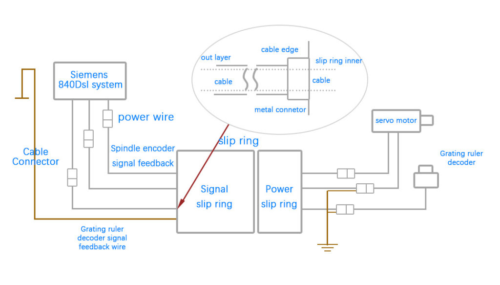
At that time, the machine tool where the conductive slip ring was located was connected to the CNC system Siemens 840DsI system. When the system is powered on and running, the CNC system will alarm and stop immediately, and the fault information is: Encoder A/B amplitude error is out of tolerance; this alarm information is interpreted as the feedback signal A phase or B of the servo motor encoder attached to the drive of the CNC system The amplitude of the phase exceeds the preset value range of the system. Test the waveform of phase B with an oscilloscope, as shown in Figure 1.
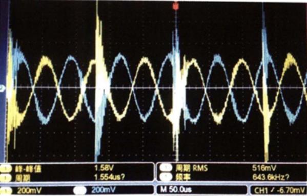
According to the Siemens encoder specification, under normal circumstances, the A-phase or B-phase waveform in the motor encoder feedback signal is a sine wave analog signal with a peak-to-peak value of 500mV, while the actual measured B-phase waveform is superimposed on the sine wave. Continuously interfering with the peak clutter signal, which caused the system to prompt the amplitude out-of-tolerance alarm.
To solve this problem, we set up an experimental system as shown in Figure 2 to further analyze the origin of the above-mentioned AVB phase interference.
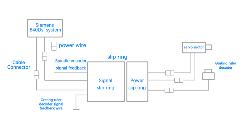
The structure of the conductive slip ring is divided into two parts: the power ring and the signal feedback loop. The power ring is a strong current ring, which is the driving power circuit output to the motor after the 600V bus voltage of the numerical control system is chopped. There are four circuits inside the power ring, which are U phase, V phase, W phase and ground. The four power lines plus the 24V brake signal line are connected to the power drive interface of the motor after passing through the power loop of the conductive slip ring; the signal feedback loop is a weak current loop, which is the feedback signal loop of the motor encoder. It is the signal loop connecting the 17-core spindle servo motor encoder and the 12-core grating encoder and the reserved signal feedback line. The alarm signal is caused by the part of the loop occupied by the feedback signal of the 17-core spindle encoder.
According to the mechanism of electromagnetic coupling, if the power ring and signal feedback loop in the conductive slip ring have not undergone effective anti-electromagnetic interference measures, it will inevitably cause the current of the power ring to affect the signal through electromagnetic coupling, electrostatic coupling, and ground current conduction. Interference in the feedback loop distorts the signal waveform.
1. The influence of electromagnetic space radiation interference
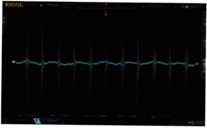
In order to confirm the distribution of electromagnetic interference in the system loop, it is convenient to further analyze the degree of interference influence and provide an effective improvement plan. In the experiment, the corresponding relationship between radiation interference induced voltage and distance was tested on multiple nodes of the system loop. The experimental results show that the radiation interference at the shielding line of the power loop is the strongest, and the interference of the power line is transmitted to the Other links, such as shielded wires, cable joints, etc., will bring high-frequency pulsations, which will radiate to space and cause short-distance the isolated conductor generates induced voltage, and the pulsating induced voltage gradually decays with the distance. The closer the distance to the power line, the stronger the induced interference voltage. The induced voltage we tested at the ground loop close to the power line is shown in Figure 3 Show.
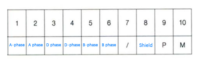
The shielding layer of the cable is grounded, so the pulsating interference in the ground loop will inevitably lead to the same pulsating interference in the shielding layer loop in the conductive slip ring. We further show the distribution of the rings where the encoder signal A phase and B phase are located in the conductive slip ring as shown in Table 1. Here, only a few rings adjacent to the A phase and the B phase are given.
It can be seen from Table 1 that the shielding layer ring will cause radiation interference to the surrounding adjacent signal rings. For example, the No. 8 ring of the shielding layer will generate noise interference to its adjacent rings (such as B-, B phase). Coupling onto the analog signal distorts the signal. The signal far away from the ring of the shielding layer will have a relatively small interference effect on this noise.
2. Influence of inter-ring coupling capacitance on signal
In order to suppress common mode interference, the feedback signals A, A and B, B- of the Siemens system go through differential twisted pairs, and the outer layer is covered with a shielding layer. According to the principle of the differential operational amplifier circuit, when the common mode interference signal is coupled into the differential circuit, the interference signal will be well suppressed in the differential circuit without affecting the normal signal waveform. However, due to the difference in coupling capacitance between the rings in the conductive slip ring after the system is connected to the conductive slip ring, this difference will greatly weaken the ability of the differential circuit to suppress common-mode signals at both ends. We can analyze this situation through a simple differential equivalent circuit model, as shown in Figure 4.
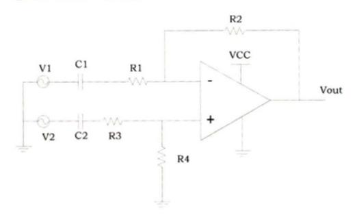
C1 and C2 in FIG. 4 respectively represent the inter-electrode coupling capacitances of the A-phase or B-phase differential loops to the ground loops of the shielding layer. When the coupling capacitors C1 and C2 are not considered, the output expression of the output Vout of the differential op amp:
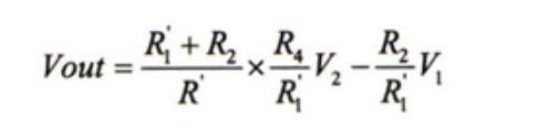
When the input terminal is a high-frequency pulsating voltage, considering the influence of coupling capacitors C1 and C2, the expression is:
When the input terminal is a high-frequency pulsating voltage, considering the influence of coupling capacitors C1 and C2, the expression is:
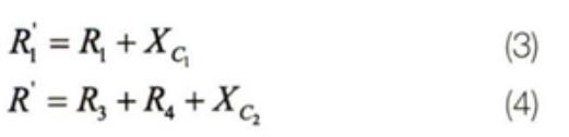
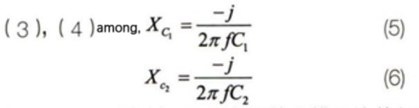
(5), (6) f in the formula is the frequency of the common mode interference coupled in.
Measured by experiment:
The common mode interference-induced voltage is:
At this time:
When the coupling capacitance is not considered, it can be obtained from formula (1)
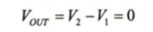
Comply with the differential circuit common mode interference suppression requirements.
When considering the influence of coupling capacitance differences, substituting the parameter test results into (2) formula gives.

When R1= R4 = 20Kohm, R2= R3 = 20Kohm,When considering the effect of coupling capacitance, from formula (2) we get.
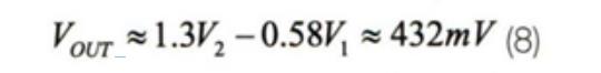
It can be known from (7) and (8) that when there is a difference in coupling capacitance and the differential circuit is disturbed by common-mode noise, that is, V1=V2, the ability of its output Vout to suppress common-mode interference is significantly weakened.
Therefore, the difference in coupling capacitance has a great influence on the common-mode rejection capability of the differential circuit. Therefore, for the inside of the conductive slip ring, the difference in the coupling capacitance between the differential input ring and the shield ring affects the common-mode interference suppression capability of the system.
Summary and Solutions
To sum up, when the conductive slip ring is connected to the system, in order to effectively suppress the electromagnetic interference of the ground loop, we have the following rectification suggestions:
(1) The incoming line end of the shell of the conductive slip ring needs to be well grounded, and it is recommended to use a wire of more than 35mm² for grounding;
(2) The outer shielded wires at the input and output ends of the signal feedback line of the conductive slip ring need to be grounded through the connection housing. Refer to Figure 5 for the connection method of the housing.
(3) Avoid the cable shielding layer from going through the loop path in the loop path of the conductive slip ring.
(4) The terminal (motor) of the conductive slip ring needs to be well grounded, that is, the machine tool where the motor is installed needs to be well grounded.
After rectification, the encoder feedback signal B phase is sampled with Siemens CNC system software, and the signal waveform obtained is shown in Figure 6, and the waveform is normal. Then conduct uninterrupted real-time observation of the electronic slip ring for more than ten days, and the numerical control system has no fault alarm.