What is waveguide switch? Teach you to know
Waveguide switch is an important component in the communication industry, and now introduce some basic knowledge here, let you rapidly know its principle and workflow.
1. Basic structure and principle of waveguide switch
The waveguide switch is used to switch the direction of the radar transmission signal, and the mechanical action is driven by electromagnetic action. Like a railway switch, the waveguide controls whether the emitted electromagnetic wave goes to the antenna or to the high-power terminal load. When the antenna scans from a low elevation angle to a high elevation angle, the waveguide switch points to the antenna, and when the antenna jumps from a high elevation angle to a low elevation angle, the waveguide switch points to the load at the end of a volume scan. The working mechanism of the waveguide switch can not only prevent the echo signal received by the antenna from entering the transmission channel but also absorb the redundant radio frequency signal generated by the transmitter in the load.
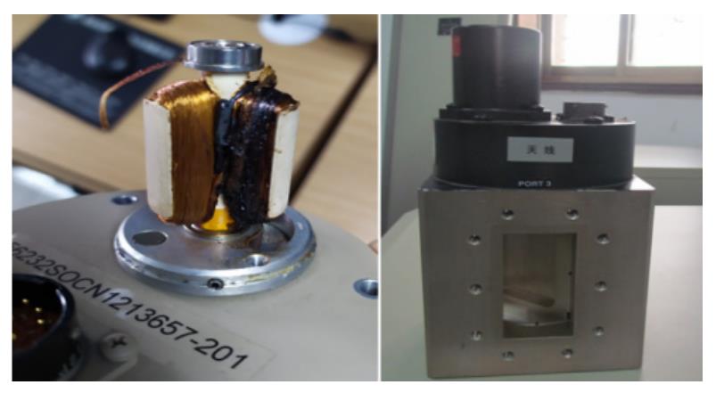
The waveguide switch consists of a drive motor, a bearing, and a pointing state limit switch. There is one holding coil, one driving coil, and two coils in the driving motor.
When the waveguide switch rotates, the drive coil of the motor is connected to the +28V voltage from the DAU power supply. After the rotation is in place, the drive coil is powered off, and the coil is kept connected to the 28V voltage. The drive and state control circuit of the waveguide switch is shown in Figure 2.
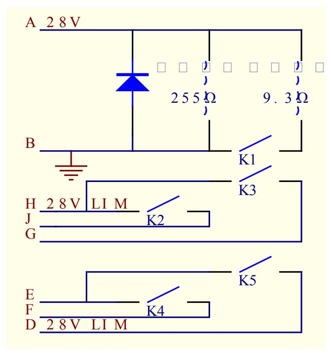
Among them, the D and H ports indicate the normal/chain state of the antenna (the antenna is reported as normal at 0V, and the chain fault is reported at 28v), the E port indicates that the waveguide switch is in a steady state or transient state, the F port indicates the command to start the switch pointing to the antenna, and the J port indicates feedback The switch points to the antenna or the load. There are four PORT surfaces under the waveguide switch, corresponding to different positions, among which PORT1 is connected to the waveguide channel of the transmitter, PORT2 is connected to a high-power load, PORT3 is sealed, and PORT4 is connected to the waveguide channel entering the antenna.
The waveguide switch points to a high-power load in the standby state of the radar, and the waveguide switch can only be driven after receiving the start command when the antenna is in a normal state. The waveguide switch points to the start signal flow of the antenna (signal identification on the back of the DAU base board) Digital board PANT CMD → analog board ANT CMD RELAY → control XK3 relay → ANT CMD and RAD HATCH SW#1 conduction, safety switch for upper fiberboard and downlink Signal FO CMD RELAY controls XK1 relay to close, RAD HATCH SW #1 conducts +28V, and finally the waveguide switch start command ANT CMD connects 28V.
2. Waveguide switch workflow
Let’s take the CINRAD/SA Doppler weather radar as an example. The radar transmitter amplifies the signal through a high-frequency amplification link to form a high-power radio frequency signal. After passing through the waveguide channel to the outside of the transmitter cabinet, it passes through the coupler, harmonic filter, circulator, spectrum filter, and directional coupler IDC2 successively, and then IDC2 sends the RF capability to the waveguide switch. Under the control of the main control program of the RDA computer, the high-power radio frequency signal is sent to the antenna/antenna base by switching the waveguide switch, and then sent to the antenna feed source through the T/R circulator, the azimuth and pitch joint direction coupler (two-way) launch out.
DAU components are mainly composed of DAU digital board, DAU analog board, DAU bottom board, and lower optical transceiver circuit board. Responsible for the communication between the RDA computer and hardware equipment such as radar transmitters and receivers, mainly through the RS-232 communication interface protocol for data transmission.
The transmitted data mainly includes transmitter control command, radar antenna position, speed, status, control command, and BIT (Build In Test) data; tower/mains command, status, and BITE data; maintenance panel data, etc. These data include analog quantity and digital quantity, and some directly use binary code and connect with RDA computers through RS-232 serial communication interface.
In the normal working state, the radar console RCW sends ANTENNACMD (direction command to the antenna), and the relay XK3 on the DAU bottom board acts, so that the driving coil is connected to the 28v DC power of the DAU power supply, and the waveguide switch starts to rotate. When PORT4 is turned on, the driving coil is turned off. Keep the coil connected to 28V DC, and keep the waveguide switch at the open position of PORT4, the RF signal comes out from the transmitter, enters the waveguide switch from PORT1, and enters the waveguide channel of the antenna through PORT4.
When the radar is in the system calibration or standby state, the radar console RCW sends ANTENNA POS IND (pointing to the load command), and the relays XK1 and XK3 on the DAU bottom board act, so that the holding coil is disconnected from the 28V DC, and the waveguide switch returns to the open position of the PORT2 port, the RF signal comes out from the transmitter, enters the waveguide switch from PORT1, and enters the load through PORT2.